This project is sourced from another site, not written by us — this list is our best match of their components against what we stock, not a verified bill of materials. Always check the original blog (linked above) for the actual parts list before buying.
This list includes a generic resistor set
as a placeholder — it is not matched to the exact value or part number this circuit needs. The correct one is specified on the original source page linked above; check it before buying.
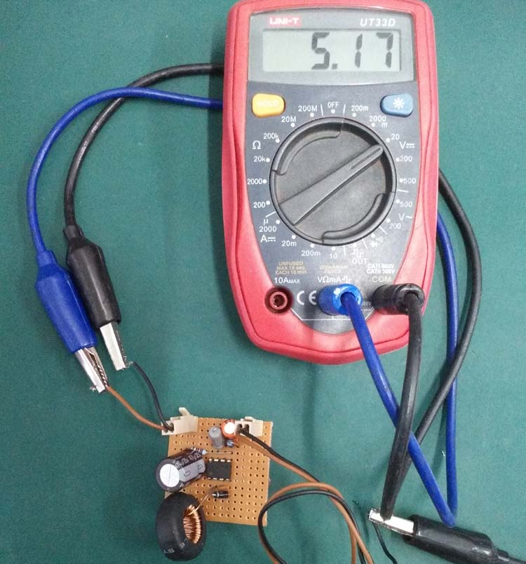
This circuit operates as a step-down buck converter, utilizing the MC34063 switching regulator IC to efficiently convert a 12V DC input down to a stable 5V DC output. At the heart of the system, the MC34063 contains an internal temperature-compensated reference, a comparator, a duty cycle oscillator, and an active switch transistor. The 470pF ceramic disc capacitor connected to the IC sets the internal oscillator timing and switching frequency. When the internal switch closes, current flows from the 12V input through the inductor (rated between 62.87uH and 100uH at 1.5A or higher) to the output, magnetically storing energy in the inductor core while simultaneously charging the 470uF 25V output capacitor. When the switch opens, the magnetic field collapses, and the inductor maintains continuous current flow to the load via the 1N5819 Schottky freewheeling diode, which provides a low-voltage-drop return path. Feedback resistors—specifically the 2k ohm and 6.2k ohm resistors—form a voltage divider that feeds a sample of the output voltage back to the IC's internal comparator to regulate the duty cycle. Additionally, a current sense resistor (~0.26 to 0.3 ohm) is integrated into the circuit to monitor peak current and provide overcurrent protection by disabling the switch if current exceeds safe thresholds. Relimate connectors facilitate clean input and output wire interfacing, all assembled permanently on Veroboard or perfboard using a soldering iron, flux, and solder wire.
Why Build This
Design a reliable, custom power supply for stepping down vehicle battery voltage (12V) to safely power 5V microcontroller circuits and embedded electronics.
Understand discrete switch-mode power supply topologies by calculating component values and assembling a functional buck converter on perfboard.
Power USB-based devices and digital logic modules efficiently without relying on inefficient linear voltage regulators that dissipate excessive heat.
Real-World Application
Stepping down vehicle battery voltage (12V) to power 5V microcontroller circuits, USB-powered devices, and various embedded electronics.
Skills You'll Learn
Switch-mode power supply design
voltage regulation principles
inductor energy storage utilization
PCB/perfboard layout and soldering
current sensing and protection circuit implementation
Safety Precautions
Exercise caution when testing live circuits with power supplies. Ensure proper polarity to avoid component damage.
Technology Tags
BUCK CONVERTER
MC34063
POWER ELECTRONICS
VOLTAGE REGULATION
DC-DC CONVERSION
SOLDERING
Frequently Asked Questions
A buck converter is a switching regulator that stores and transfers energy efficiently, resulting in much less wasted heat compared to a linear regulator when dropping 12V down to 5V at higher currents.
The 1N5819 is a Schottky diode that acts as a freewheeling or flyback diode, providing a safe return path for inductor current when the internal switch turns off, preventing damaging voltage spikes.
Yes, the output voltage is determined by the ratio of the feedback resistors (the 2k ohm and 6.2k ohm resistors). Changing their values adjusts the voltage divider ratio sampled by the MC34063 comparator.
Gallery
This page is part of Kitkraft's Project Hub — a curated collection of electronics & robotics projects gathered from the maker community to help students and hobbyists discover and learn to build. Kitkraft does not claim authorship of the original project, and makes no representation as to the accuracy, completeness or safety of third-party source material. The summary and "How It Works" explanation above are AI-generated, rewritten with reference to the original tutorial — not a reproduction of it. Full credit and a direct link to the original source are provided above. If you're the original creator and have a concern about how your work is represented here, please contact us and we'll address it promptly.
 10pcs - 220 ohm 1/4 W Resistor Set
Rs. 39.00
 Jumper Wire 10 Pin Male To Male 20cm
Rs. 45.00
 400 Points Mini Solderless Prototype PCB Breadboard High Quality
Rs. 89.00
 MB102 Adjustable Breadboard Power Supply Module (3.3V & 5V) for Arduino & Raspberry Pi
Rs. 139.00
 Jumper Wire 10 Pin Male To Female 20cm
Rs. 45.00


