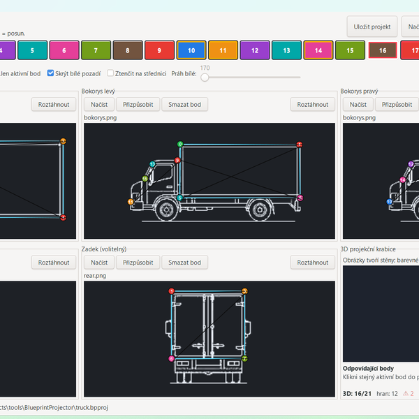
A software application that converts multiple orthographic blueprint views into a rotatable 3D wireframe model, which can be exported as a 3D DXF file.
We stock the boards, sensors and modules this project needs. A full parts list is coming soon — for now, browse our DIY Kits & components or search for Analog / Discrete parts.
The 3D Wireframe Generator from Blueprint Images is a software-based system operating on a Windows PC that processes orthographic projection files to construct interactive three-dimensional models. Utilizing the custom BlueprintProjector software (.bpproj), the application takes multiple two-dimensional views—typically top, front, and side profiles from blueprints—and maps them into a shared spatial coordinate system. By aligning the corresponding geometric features, vertices, and edges across the distinct 2D planes, the software triangulates and reconstructs the data into a unified, rotatable 3D wireframe. Users can manipulate the resulting model directly on their PC interface to inspect spatial relationships and volumetric accuracy. Once the wireframe representation is finalized, the software compiles the spatial coordinate data and translates it into an industry-standard 3D DXF file format, allowing the generated wireframe to be seamlessly imported into standard CAD suites and external modeling environments for further engineering analysis.
Why Build This
Rapidly translate legacy 2D paper or scanned technical drawings into functional 3D CAD-compatible wireframes for vehicle and product modeling.
Bridge the gap between orthographic multi-view drafting and spatial geometry reconstruction for engineering design coursework.
Streamline the rapid prototyping pipeline by automating the coordinate alignment of multiple blueprint perspectives into a single exportable wireframe.
Real-World Application
Rapid prototyping, turning 2D paper or scanned blueprints into 3D CAD-compatible wireframes for vehicle or product modeling.
Skills You'll Learn
orthographic projection analysis
3D spatial coordinate mapping
geometry reconstruction
CAD file formatting
multi-view data alignment
Safety Precautions
No specific precautions noted for this build — always follow general electronics safety practices.
Technology Tags
PYTHON
3D MODELING
DXF EXPORT
COMPUTER VISION
IMAGE PROCESSING
GUI
Frequently Asked Questions
The application is designed specifically for a Windows PC environment.
Projects use custom .bpproj files for input data, and the final 3D models can be exported as standard 3D DXF files for CAD compatibility.
No, this is an analog and software-based build running on a Windows PC without requiring a dedicated hardware development board.
Gallery
This page is part of Kitkraft's Project Hub — a curated collection of electronics & robotics projects gathered from the maker community to help students and hobbyists discover and learn to build. Kitkraft does not claim authorship of the original project, and makes no representation as to the accuracy, completeness or safety of third-party source material. The summary and "How It Works" explanation above are AI-generated, rewritten with reference to the original tutorial — not a reproduction of it. Full credit and a direct link to the original source are provided above. If you're the original creator and have a concern about how your work is represented here, please contact us and we'll address it promptly.
Kitkraft Project Hub — curated from the maker community, credited at the source.