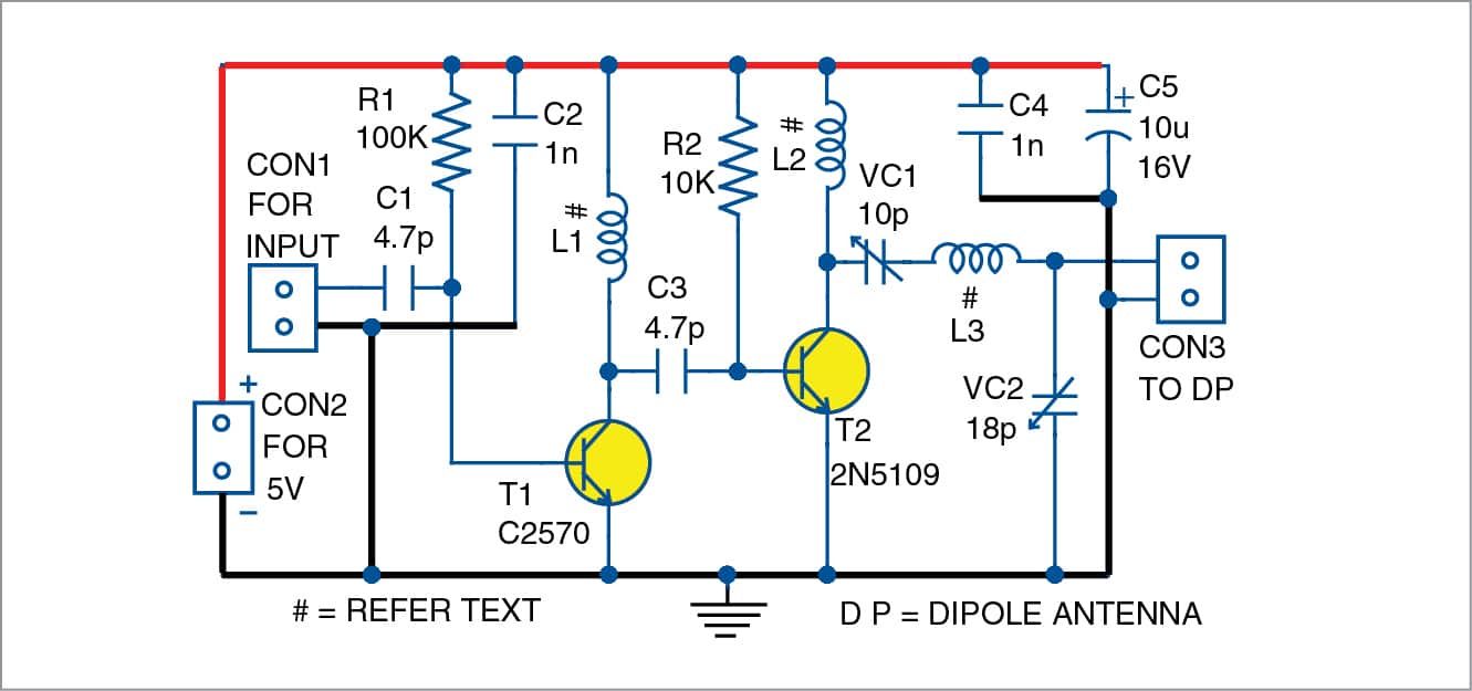
This 433MHz RF Range Extender circuit increases the wireless operation range to almost double by amplifying the signal using C2570 and 2N5109 transistors.
This project is sourced from another site, not written by us — this list is our best match of their components against what we stock, not a verified bill of materials. Always check the original blog (linked above) for the actual parts list before buying.
This list includes a generic resistor set
as a placeholder — it is not matched to the exact value or part number this circuit needs. The correct one is specified on the original source page linked above; check it before buying.
The 433MHz RF Range Extender is an analog repeater circuit designed to capture, amplify, and retransmit radio frequency signals in the popular 433MHz industrial, scientific, and medical (ISM) band, effectively doubling the operational range of wireless devices. Operating on a 5V DC power supply, the circuit utilizes a single-side PCB layout to host a discrete amplification stage driven by specialized high-frequency transistors, specifically the C2570 (T1) and the 2N5109 (T2). Incoming weak RF signals are captured by a dipole antenna or coaxial cable connected to the input connectors. These signals are coupled into the tuning network, where custom inductor coils (L1, L2, L3) wound from 24 SWG enameled copper wire and variable trimmer capacitors (VC1, VC2) form resonant LC tank circuits. These tuned circuits allow the builder to precisely calibrate the operational frequency to 433MHz, ensuring maximum power transfer and selectivity. Transistors T1 and T2 act as high-frequency RF amplifiers, boosting the signal amplitude to overcome path loss, obstacles, and atmospheric attenuation. Once amplified, the stronger signal is routed through the output connectors (CON1, CON2, CON3) and radiated back into space via the antenna. Passive resistors and capacitors distributed throughout the schematic establish proper DC biasing points, stabilize the transistor gain, and filter out high-frequency noise or power supply ripple, ensuring stable linear amplification without parasitic oscillations.
Why Build This
Design and optimize discrete high-frequency RF amplifier stages using specialized transistors like the C2570 and 2N5109 for undergraduate-level communication system studies.
Gain practical experience tuning analog LC resonant circuits at 433MHz using variable trimmer capacitors and custom hand-wound copper coils.
Solve real-world signal attenuation challenges in wireless sensor networks, home automation, and remote control systems.
Real-World Application
Improving range for remote control systems, wireless sensors, garage door openers, and home automation devices operating on the 433MHz frequency band.
Skills You'll Learn
RF amplifier design
LC tank circuit tuning
impedance matching
high-frequency transistor biasing
hand-winding inductive coils
PCB layout for analog radio frequencies
Safety Precautions
Ensure proper power supply voltage (5V DC) and correct polarity to avoid damaging active transistors and RF modules.
Technology Tags
RF
433MHZ
TRANSMITTER
RECEIVER
WIRELESS
UHF AMPLIFIER
TRANSISTOR C2570
2N5109
PCB DESIGN
ANTENNA
Frequently Asked Questions
Variable trimmer capacitors (VC1, VC2) allow you to finely adjust the resonant frequency of the LC tank circuits to precisely 433MHz, compensating for small manufacturing tolerances in the hand-wound coils and stray capacitance on the breadboard or PCB.
No, you must use the specified 24 SWG enameled copper wire. The wire gauge and physical dimensions of the coil determine its inductance value, which is critical for hitting the 433MHz frequency band.
No, this is a purely analog discrete hardware build with no microcontrollers or firmware required; its performance relies entirely on physical component tuning and analog signal amplification.
Gallery
This page is part of Kitkraft's Project Hub — a curated collection of electronics & robotics projects gathered from the maker community to help students and hobbyists discover and learn to build. Kitkraft does not claim authorship of the original project, and makes no representation as to the accuracy, completeness or safety of third-party source material. The summary and "How It Works" explanation above are AI-generated, rewritten with reference to the original tutorial — not a reproduction of it. Full credit and a direct link to the original source are provided above. If you're the original creator and have a concern about how your work is represented here, please contact us and we'll address it promptly.
 MB102 Adjustable Breadboard Power Supply Module (3.3V & 5V) for Arduino & Raspberry Pi
Rs. 139.00
 10pcs - 220 ohm 1/4 W Resistor Set
Rs. 39.00
 400 Points Mini Solderless Prototype PCB Breadboard High Quality
Rs. 89.00
 Jumper Wire 10 Pin Male To Male 20cm
Rs. 45.00
 Jumper Wire 10 Pin Male To Female 20cm
Rs. 45.00


