This project is sourced from another site, not written by us — this list is our best match of their components against what we stock, not a verified bill of materials. Always check the original blog (linked above) for the actual parts list before buying.
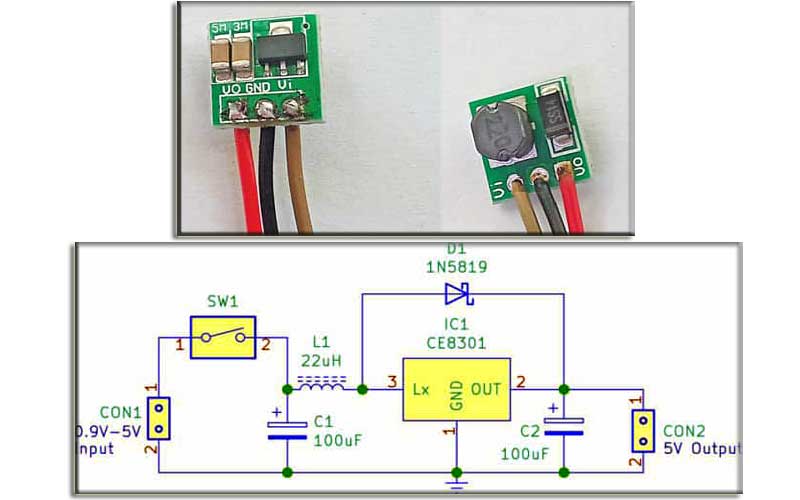
The 5V Boost Converter Circuit is designed to step up a low input voltage, such as that from a single 1.5V battery cell, to a steady 5V output. At the heart of the circuit is the CE8301 integrated circuit (IC1), which functions as a DC-DC step-up switching regulator. When the on-off switch (SW1) is closed, current flows from the input cell through the 22µH inductor (L1) and into the switching elements inside the CE8301. The IC rapidly toggles an internal switch to store and release magnetic energy in the inductor, generating voltage spikes that are higher than the input source. The 1N5819 Schottky barrier diode (D1) acts as a high-speed rectifier, allowing current to flow unidirectionally from the inductor to the output while preventing reverse current leakage; Schottky diodes are chosen here for their low forward voltage drop and fast switching speeds, which maximize overall efficiency. Input and output filtering are handled by the two 100µF, 16V electrolytic capacitors (C1 and C2). C1 stabilizes the input voltage rail against sudden current demands, while C2 smooths out the switched voltage pulses to deliver a stable, continuous 5V DC output to the load. Two 2-pin connectors provide convenient connection points for the input power source and the output load. Because this is a discrete analog power supply design, no software programming is required; regulation is achieved entirely through the hardware component interactions.
Why Build This
Design and analyze a discrete switch-mode power supply to understand the principles of voltage step-up conversion.
Evaluate the efficiency and transient response of a boost topology using inductive energy storage and Schottky rectification.
Power miniature low-voltage electronic prototypes or portable gadgets directly from a single depleted or low-voltage battery cell.
Real-World Application
Powering portable low-voltage electronic devices such as wireless mice, remote controls, and miniature gadgets from a single battery cell.
Skills You'll Learn
DC-DC boost converter design
inductive energy storage analysis
Schottky diode rectification
power supply decoupling and filtering
switch-mode power regulation
Safety Precautions
No specific precautions noted for this build — always follow general electronics safety practices.
Technology Tags
BOOST CONVERTER
DC-DC CONVERTER
POWER MANAGEMENT
PFM
CE8301
Frequently Asked Questions
A Schottky barrier diode like the 1N5819 features a very low forward voltage drop and extremely fast switching characteristics, which minimize power losses and improve the overall efficiency of the boost conversion process.
The 22µH inductor value is specifically chosen to match the operating frequency and internal parameters of the CE8301 IC; changing this value significantly can alter the output current capacity, ripple, and stability of the converter.
No, this is a purely hardware-based analog circuit. The CE8301 IC autonomously handles the switching and regulation without requiring any software or code.
Gallery
This page is part of Kitkraft's Project Hub — a curated collection of electronics & robotics projects gathered from the maker community to help students and hobbyists discover and learn to build. Kitkraft does not claim authorship of the original project, and makes no representation as to the accuracy, completeness or safety of third-party source material. The summary and "How It Works" explanation above are AI-generated, rewritten with reference to the original tutorial — not a reproduction of it. Full credit and a direct link to the original source are provided above. If you're the original creator and have a concern about how your work is represented here, please contact us and we'll address it promptly.
Kitkraft Project Hub — curated from the maker community, credited at the source.
 2-Slot 18650 Holder with Protective Cover and On/Off Switch – Case
Rs. 109.00
 400 Points Mini Solderless Prototype PCB Breadboard High Quality
Rs. 89.00
 MB102 Adjustable Breadboard Power Supply Module (3.3V & 5V) for Arduino & Raspberry Pi
Rs. 139.00
 Jumper Wire 10 Pin Male To Male 20cm
Rs. 45.00
 Jumper Wire 10 Pin Male To Female 20cm
Rs. 45.00


