This project is sourced from another site, not written by us — this list is our best match of their components against what we stock, not a verified bill of materials. Always check the original blog (linked above) for the actual parts list before buying.
This list includes a generic resistor set
as a placeholder — it is not matched to the exact value or part number this circuit needs. The correct one is specified on the original source page linked above; check it before buying.
We don't carry yet: Logic ICs (74xx / 40xx)
Transistors (BC547 / 2N2222 / TIP / MOSFET)
Water Level / Float Sensor
Water Pump / Valve
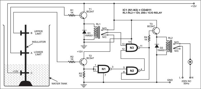
The Automatic Water Pump Controller circuit operates as a closed-loop feedback system designed to monitor and regulate liquid levels within a storage reservoir using discrete analog and digital logic components. Powered by a stable 12V DC power supply, the system utilizes conductive probes placed at different heights inside the tank to detect the presence or absence of water. These water-level sensing probes interface with a network of BC547 transistors configured to translate subtle changes in electrical conductivity into distinct logic-level voltage signals. The core decision-making unit of the circuit is the CD4011 IC, which contains quad 2-input NAND gates. By configuring these NAND gates in a set-reset or latching logic arrangement, the circuit remembers the current state of the water tank, preventing rapid and erratic switching when water ripples near the sensor thresholds. When the water level drops below the lower limit probe, the logic state changes to drive the transistors, which in turn energize the relay designated as RL1 or RL2. These electromechanical relays act as heavy-duty switches capable of safely handling the electrical load required to turn the water pump motor on. Conversely, once the water reaches the upper limit probe, the circuit inverts its output state, de-energizing the relay and shutting off the water pump motor to prevent overflowing. Through this continuous combination of probe sensing, transistor signal conditioning, NAND gate logic processing, and relay actuation, the system autonomously maintains optimal water levels without requiring manual intervention.
Why Build This
Design and analyze foundational combinational logic systems using discrete CMOS integrated circuits for real-world automation tasks.
Apply undergraduate-level principles of transistor biasing and electromechanical relay interfacing to control higher-power DC loads safely.
Develop practical troubleshooting methodologies for analog sensor interfaces and feedback control loops in electrical engineering.
Real-World Application
Automated domestic and industrial water tank management to prevent overflowing and dry-running of water pumps.
Skills You'll Learn
Combinational logic gate design
transistor switching and biasing
electromechanical relay interfacing
analog sensor signal conditioning
low-voltage power distribution
Safety Precautions
Ensure proper insulation and safety when dealing with 12V DC power supplies and water level sensing probes.
Technology Tags
CD4011
NAND GATE
TRANSISTORS
BC547
RELAYS
WATER LEVEL CONTROLLER
MOTOR CONTROL
ANALOG ELECTRONICS
DIY ELECTRONICS
Frequently Asked Questions
No, this is a purely analog and discrete logic project controlled entirely by the CD4011 NAND gate IC and transistor circuitry, so no software or programming is required.
The BC547 transistors act as electronic switches and signal amplifiers that take the weak electrical signals from the water level sensing probes and boost them to levels capable of driving the relays.
The project operates on a 12V DC power supply, and the relays are designed to manage low-voltage DC switching. Connecting high-voltage AC mains directly requires strict adherence to safety standards and proper relay isolation ratings not covered in a basic DC setup.
Gallery
This page is part of Kitkraft's Project Hub — a curated collection of electronics & robotics projects gathered from the maker community to help students and hobbyists discover and learn to build. Kitkraft does not claim authorship of the original project, and makes no representation as to the accuracy, completeness or safety of third-party source material. The summary and "How It Works" explanation above are AI-generated, rewritten with reference to the original tutorial — not a reproduction of it. Full credit and a direct link to the original source are provided above. If you're the original creator and have a concern about how your work is represented here, please contact us and we'll address it promptly.
Kitkraft Project Hub — curated from the maker community, credited at the source.
 5V 1 Channel Relay Module
Rs. 45.00
 10pcs - 220 ohm 1/4 W Resistor Set
Rs. 39.00
 MB102 Adjustable Breadboard Power Supply Module (3.3V & 5V) for Arduino & Raspberry Pi
Rs. 139.00
 400 Points Mini Solderless Prototype PCB Breadboard High Quality
Rs. 89.00
 Jumper Wire 10 Pin Male To Male 20cm
Rs. 45.00
 Jumper Wire 10 Pin Male To Female 20cm
Rs. 45.00


