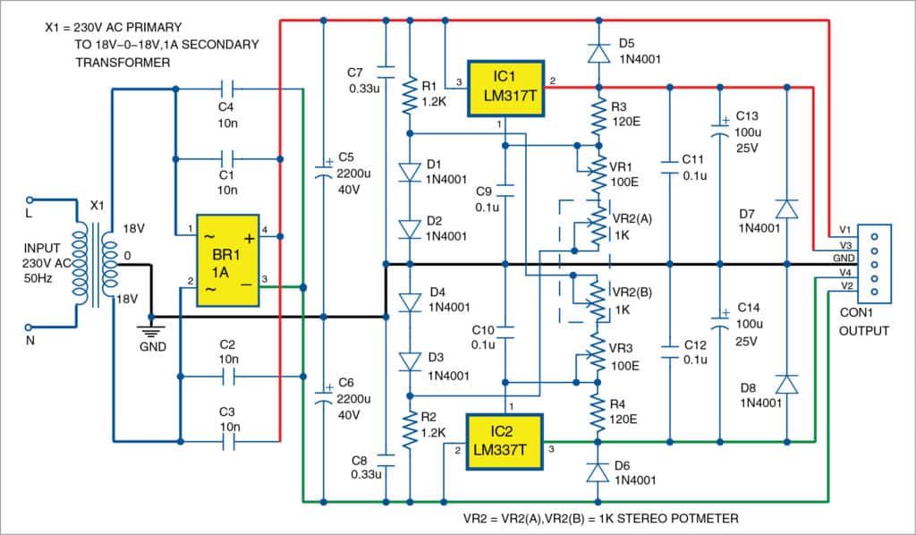
A circuit for a bipolar power supply using LM317T and LM337T adjustable voltage regulators, providing precise simultaneous voltage adjustment near ground levels.
This project is sourced from another site, not written by us — this list is our best match of their components against what we stock, not a verified bill of materials. Always check the original blog (linked above) for the actual parts list before buying.
This bipolar power supply circuit converts standard 230V AC mains electricity into symmetrical, adjustable positive and negative DC voltages suitable for powering dual-rail analog systems. The process begins with an 18V-0-18V step-down transformer (X1), which reduces the high mains voltage to lower, safer AC levels with a center tap providing a 0V reference. The AC output passes through a 1A bridge rectifier (BR1) and an arrangement of eight 1N4001 diodes (D1 through D8) to perform full-wave rectification, converting the alternating current into pulsating direct current. Large filter capacitors C5 and C6 (rated at least 2200µF and 40V) smooth out the voltage ripples from the rectified output, establishing stable pre-regulation DC rails. To provide precise control over the output voltage, the positive rail uses an LM317T variable positive-voltage regulator (IC1), while the negative rail employs an LM337T variable negative-voltage regulator (IC2). A dual-gang stereo potentiometer, designated as VR2(A) combined with VR2(B), allows a user to simultaneously adjust both the positive and negative output voltages near ground levels with high symmetry. Because linear regulators dissipate excess voltage as heat, physical heat-sinks are attached to IC1 and IC2 to ensure thermal stability and prevent component damage during operation, especially when delivering higher current loads to the output.
Why Build This
Design and characterize a dependable dual-rail DC power source required for testing undergraduate-level analog integrated circuits and operational amplifier topologies.
Gain practical experience in implementing active linear regulation using adjustable positive and negative IC regulators alongside center-tapped transformer configurations.
Evaluate the thermal management requirements and ripple rejection performance of linear power supplies under varying load conditions.
Real-World Application
Used as a bench power supply for testing operational amplifiers, analog circuits, and dual-rail electronic systems that require symmetrical positive and negative voltages.
Skills You'll Learn
AC-to-DC power conversion
linear voltage regulation
dual-rail circuit design
thermal management with heat-sinks
ripple filtering with electrolytic capacitors
Safety Precautions
Exercise caution when working with 230V AC mains voltage connected to the primary coil of the step-down transformer. Ensure proper heat-sinking for regulators to prevent overheating during high current output.
Technology Tags
POWER SUPPLY
LM317T
LM337T
VOLTAGE REGULATOR
ANALOG ELECTRONICS
TRANSFORMER
BRIDGE RECTIFIER
PCB DESIGN
Frequently Asked Questions
The LM317T is designed specifically to regulate positive voltages, while the LM337T is its complementary counterpart engineered to regulate negative voltages. Both are necessary to achieve symmetrical dual-rail outputs from a single power supply.
The stereo potentiometer links the adjustment pins of both the positive and negative regulators mechanically, allowing you to tune the positive and negative output voltages simultaneously and symmetrically using a single control knob.
Yes. Linear regulators drop excess voltage across themselves as heat. Without proper heat-sinks, the regulators will quickly overheat and trigger internal thermal shutdown, limiting the maximum current output of the supply.
Gallery
This page is part of Kitkraft's Project Hub — a curated collection of electronics & robotics projects gathered from the maker community to help students and hobbyists discover and learn to build. Kitkraft does not claim authorship of the original project, and makes no representation as to the accuracy, completeness or safety of third-party source material. The summary and "How It Works" explanation above are AI-generated, rewritten with reference to the original tutorial — not a reproduction of it. Full credit and a direct link to the original source are provided above. If you're the original creator and have a concern about how your work is represented here, please contact us and we'll address it promptly.
 LM2596 Step Down DC-DC Buck Converter
Rs. 99.00
 DC Motor Plastic Fan Blade
Rs. 19.00
 400 Points Mini Solderless Prototype PCB Breadboard High Quality
Rs. 89.00
 MB102 Adjustable Breadboard Power Supply Module (3.3V & 5V) for Arduino & Raspberry Pi
Rs. 139.00
 Jumper Wire 10 Pin Male To Male 20cm
Rs. 45.00
 Jumper Wire 10 Pin Male To Female 20cm
Rs. 45.00


