Project Hub
/Healthcare Biomedical & Assistive/Pulse Oximeter & Vital Scanner/Build Your Own Simple Smartwatch
Intermediate
ESP32
Project Specific
3 – 6 Hours
Partial Kit
Build Your Own Simple Smartwatch
Build your own programmable smartwatch using an IndusBoard Coin, GC9A0 display, and various health sensors to track vital signs like heart rate, SpO2, and body temperature.
This project is sourced from another site, not written by us — this list is our best match of their components against what we stock, not a verified bill of materials. Always check the original blog (linked above) for the actual parts list before buying.
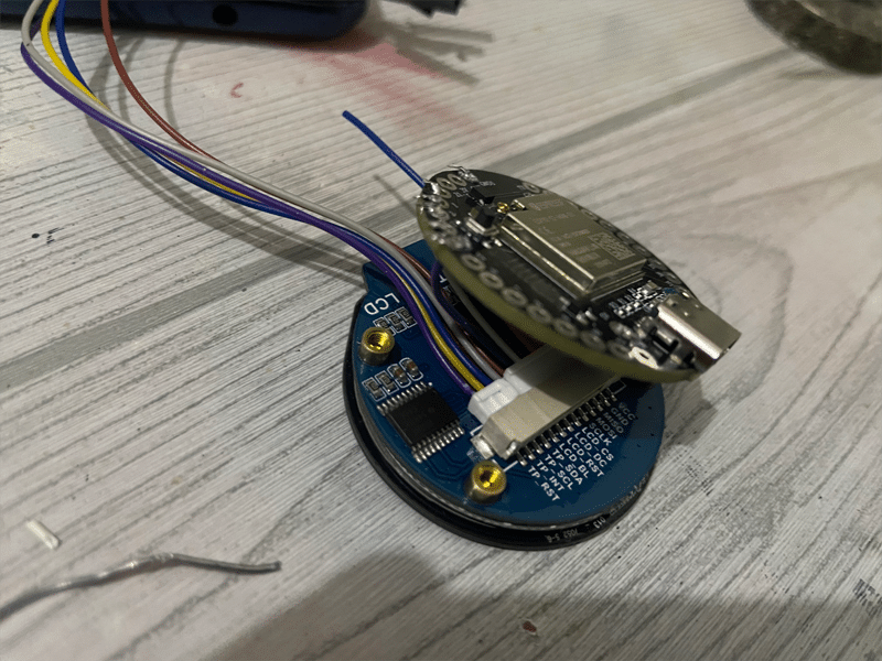
The Simple Smartwatch system centers around the IndusBoard Coin microcontroller, which acts as the core processing unit for gathering sensor data and rendering the graphical user interface. To monitor vital signs, the device integrates a MAX30100 sensor module, which utilizes optical plethysmography—emitting specific wavelengths of light through the skin to measure changes in light absorption caused by pulsating blood flow, thereby calculating both heart rate and blood oxygen saturation (SpO2). Body temperature data is captured via an integrated temperature sensor wired into the microcontroller. Once raw measurements are processed by the ESP32-based IndusBoard Coin, the user interface and real-time health metrics are outputted visually to a vibrant GC9A0 display screen, allowing the wearer to view their vital signs directly on the wrist. Communication between the microcontroller and its peripheral sensors relies on standard digital communication protocols, while power management and physical assembly are achieved using connecting wires and standard soldering equipment to secure the hardware into a cohesive, wearable unit programmed via the Arduino IDE.
Why Build This
Design and prototype a functional, wearable IoT biomedical device suitable for undergraduate engineering capstone or portfolio demonstrations.
Implement real-world health data collection by interfacing optical and thermal sensors with a microcontroller.
Explore wireless mesh networking potential for remote patient monitoring and community health data collection.
Real-World Application
Personal health tracking, remote patient monitoring, and community health data collection through mesh networking.
Skills You'll Learn
Microcontroller programming
I2C communication protocol
optical sensor data acquisition
display interfacing
wearable hardware integration
Safety Precautions
No specific precautions noted for this build — always follow general electronics safety practices.
Technology Tags
WEARABLES
IOT
HEALTH MONITORING
ARDUINO IDE
WI-FI
EMBEDDED SYSTEMS
SENSORS
Frequently Asked Questions
Yes, because the IndusBoard Coin is built around the ESP32 platform, you can also use environments like ESP-IDF or MicroPython, though the project documentation and libraries are primarily tailored for the Arduino IDE.
The vital signs are rendered in real-time onto the GC9A0 color display connected directly to the microcontroller.
Basic to intermediate soldering skills are needed to securely connect the wires, sensors, and microcontroller together into a reliable wearable form factor.
Gallery
This page is part of Kitkraft's Project Hub — a curated collection of electronics & robotics projects gathered from the maker community to help students and hobbyists discover and learn to build. Kitkraft does not claim authorship of the original project, and makes no representation as to the accuracy, completeness or safety of third-party source material. The summary and "How It Works" explanation above are AI-generated, rewritten with reference to the original tutorial — not a reproduction of it. Full credit and a direct link to the original source are provided above. If you're the original creator and have a concern about how your work is represented here, please contact us and we'll address it promptly.
Kitkraft Project Hub — curated from the maker community, credited at the source.
 Jumper Wire 10 Pin Male To Male 20cm
Rs. 45.00
 400 Points Mini Solderless Prototype PCB Breadboard High Quality
Rs. 89.00
 MB102 Adjustable Breadboard Power Supply Module (3.3V & 5V) for Arduino & Raspberry Pi
Rs. 139.00
 Jumper Wire 10 Pin Male To Female 20cm
Rs. 45.00


