This project is sourced from another site, not written by us — this list is our best match of their components against what we stock, not a verified bill of materials. Always check the original blog (linked above) for the actual parts list before buying.
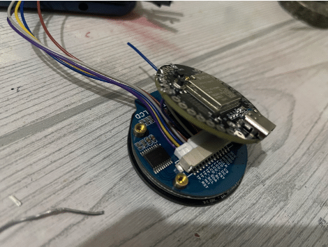
The Versatile Smart Speed Dial system functions by combining the processing power of the IndusBoard (or IndusBoard Coin) with a vibrant GC9A01 round TFT LCD display. At the core of the system, the microcontroller running on the IndusBoard executes custom firmware written through the Arduino IDE. This program leverages the TFT_eSPI graphics library to drive the GC9A01 display, which communicates via a high-speed serial interface like SPI. The IndusBoard processes input logic, calculates appropriate gauge metrics or status updates, and continuously renders dynamic graphical elements onto the circular screen. Through precise pixel mapping and hardware-accelerated drawing functions provided by the graphics library, the circular display updates smoothly to represent real-time data such as simulated speeds, fuel levels, or sensor readouts. Physical assembly relies on solid wiring and secure soldering techniques to connect the display pins to the appropriate SPI and power pins on the IndusBoard, ensuring stable data transmission and power delivery for continuous interactive operation.
Why Build This
Develop custom graphical user interfaces and round gauge readouts for advanced embedded systems engineering prototypes.
Integrate high-resolution circular TFT displays with modern microcontroller development boards using industry-standard libraries.
Design specialized visual indicators applicable to automotive dashboards, digital speedometers, and remote sensor monitoring stations.
Real-World Application
Automotive dashboards, digital speedometers, fuel meters, sensor data monitors, and directional indicators.
Skills You'll Learn
Embedded display interfacing
SPI communication protocol
graphics library implementation
microcontroller firmware development
hardware soldering and wiring
Safety Precautions
No specific precautions noted for this build — always follow general electronics safety practices.
Technology Tags
INDUSBOARD
GC9A01 DISPLAY
ARDUINO IDE
TFT_ESPI LIBRARY
SPI COMMUNICATION
EMBEDDED DISPLAY
SMART DIAL
Frequently Asked Questions
The project code and UI layout are specifically tailored for the circular GC9A01 display using the TFT_eSPI library, so a rectangular display would require significant code and layout modifications.
You will need the Arduino IDE installed on your computer along with the TFT_eSPI library configured for your display and board architecture.
Basic soldering skills are needed to securely attach header pins or connecting wires between the IndusBoard and the GC9A01 display for reliable communication.
Gallery
This page is part of Kitkraft's Project Hub — a curated collection of electronics & robotics projects gathered from the maker community to help students and hobbyists discover and learn to build. Kitkraft does not claim authorship of the original project, and makes no representation as to the accuracy, completeness or safety of third-party source material. The summary and "How It Works" explanation above are AI-generated, rewritten with reference to the original tutorial — not a reproduction of it. Full credit and a direct link to the original source are provided above. If you're the original creator and have a concern about how your work is represented here, please contact us and we'll address it promptly.
Kitkraft Project Hub — curated from the maker community, credited at the source.
 Jumper Wire 10 Pin Male To Male 20cm
Rs. 45.00
 400 Points Mini Solderless Prototype PCB Breadboard High Quality
Rs. 89.00
 MB102 Adjustable Breadboard Power Supply Module (3.3V & 5V) for Arduino & Raspberry Pi
Rs. 139.00
 Jumper Wire 10 Pin Male To Female 20cm
Rs. 45.00


