Building Fastest Finger First Indicator With Arduino
Project Hub
/Audio Displays & Interactive Media/LED Matrix & Cube Displays/Building Fastest Finger First Indicator With Arduino
Beginner
ARDUINO
₹1,500 – ₹5,000
3 – 6 Hours
Partial Kit
Building Fastest Finger First Indicator With Arduino
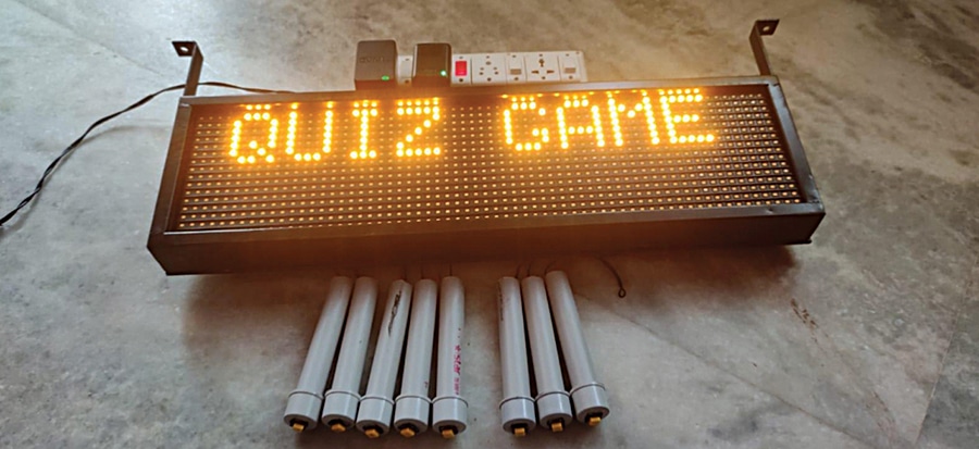
This DIY project builds a fastest finger first indicator for quiz games supporting up to eight teams, using an Arduino Mega and a P10 LED display module to show the winning team in real-time.
This project is sourced from another site, not written by us — this list is our best match of their components against what we stock, not a verified bill of materials. Always check the original blog (linked above) for the actual parts list before buying.
The Fastest Finger First Indicator system operates by monitoring eight independent push buttons (SW1 through SW8), each assigned to a different quiz team. The Arduino Mega, running code compiled through the Arduino IDE, continuously scans these input pins for a low-to-high or high-to-low state change corresponding to a button press. The moment the microcontroller registers the first valid input transition, it locks out subsequent button presses to ensure fairness and prevent later inputs from altering the result. Once the winning team's input is captured, the Arduino communicates the corresponding team number or identifier to the P10 LED display module. The P10 module renders this text or number brightly and clearly in real-time, allowing participants and audience members to immediately see who pressed first. Because P10 LED matrix panels require substantial operating current to illuminate their high-brightness surface diodes, the system utilizes two separate power supplies: one dedicated power supply safely handles the high-current demands of the P10 display, while the second power supply powers the Arduino Mega board independently. This dual-power configuration prevents voltage sags, logic resets, and electrical noise from interfering with the microcontroller's digital input scanning accuracy.
Why Build This
Design a reliable, multi-channel reaction time indicator suitable for academic quiz bowls, engineering department competitions, and interactive classroom learning environments.
Gain practical experience integrating high-current matrix displays with microcontrollers using isolated power distribution architectures to prevent system instability.
Real-World Application
Quiz competitions, game shows, interactive classroom learning, and corporate events requiring accurate reaction-time measurement.
Skills You'll Learn
Digital input debouncing
multi-channel button polling
LED matrix display interfacing
dual-power supply system integration
microcontroller state management
Safety Precautions
No specific precautions noted for this build — always follow general electronics safety practices.
Technology Tags
ARDUINO
P10 LED DISPLAY
PUSH BUTTONS
SPI
MICROCONTROLLERS
QUIZ GAME ELECTRONICS
Frequently Asked Questions
P10 LED display modules draw significant current to illuminate their matrix LEDs. Powering them directly through the Arduino's onboard regulator can cause severe voltage drops, leading to unpredictable microcontroller reboots or display flickering. Using a dedicated power supply for the P10 ensures stable operation.
The Arduino Mega executes its code sequentially at high clock speeds, registering the precise microsecond of the first detected input pin state change and immediately ignoring subsequent button states until the system is manually reset for the next round.
The Arduino Mega features a large number of digital I/O pins, making it physically possible to add more push buttons, though you would need to adjust your Arduino IDE code accordingly to scan and handle the additional inputs.
Gallery
This page is part of Kitkraft's Project Hub — a curated collection of electronics & robotics projects gathered from the maker community to help students and hobbyists discover and learn to build. Kitkraft does not claim authorship of the original project, and makes no representation as to the accuracy, completeness or safety of third-party source material. The summary and "How It Works" explanation above are AI-generated, rewritten with reference to the original tutorial — not a reproduction of it. Full credit and a direct link to the original source are provided above. If you're the original creator and have a concern about how your work is represented here, please contact us and we'll address it promptly.
Kitkraft Project Hub — curated from the maker community, credited at the source.
 2-Slot 18650 Holder with Protective Cover and On/Off Switch – Case
Rs. 109.00
 400 Points Mini Solderless Prototype PCB Breadboard High Quality
Rs. 89.00
 MB102 Adjustable Breadboard Power Supply Module (3.3V & 5V) for Arduino & Raspberry Pi
Rs. 139.00
 Jumper Wire 10 Pin Male To Male 20cm
Rs. 45.00
 Jumper Wire 10 Pin Male To Female 20cm
Rs. 45.00


