Clocked SR Flip-Flop: Complete Guide with Circuit, Truth Table, and Working
Project Hub
/Security Surveillance & Defense/Intrusion Detection Systems/Clocked SR Flip-Flop: Complete Guide with Circuit, Truth Table, and Working
Beginner
ANALOG / DISCRETE
Project Specific
3 – 6 Hours
Partial Kit
Clocked SR Flip-Flop: Complete Guide with Circuit, Truth Table, and Working
A comprehensive guide explaining the clocked SR flip-flop, including its truth table, circuit implementations using NAND and NOR gates, working principles, and practical applications.
We stock the boards, sensors and modules this project needs. A full parts list is coming soon — for now, browse our DIY Kits & components or search for Analog / Discrete parts.
This project is sourced from another site, not written by us — this list is our best match of their components against what we stock, not a verified bill of materials. Always check the original blog (linked above) for the actual parts list before buying.
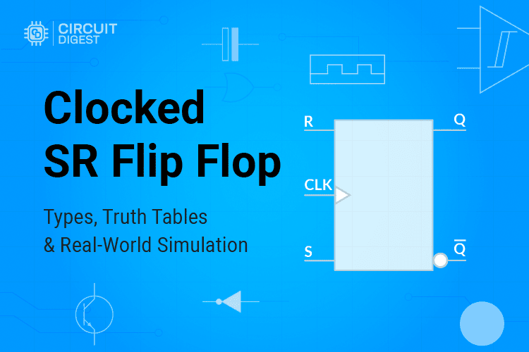
A clocked SR flip-flop is a fundamental digital memory element that stores a single bit of binary information. Unlike a basic asynchronous set-reset latch, the clocked version includes an extra input called the Clock (CLK) or enable line. This means the circuit will only respond to changes at the Set (S) and Reset (R) inputs when an active clock pulse is applied, allowing engineers to synchronize state changes with a timing signal. The circuit can be constructed using discrete logic gates, specifically either NAND or NOR gates arranged in a cross-coupled feedback configuration. When the clock pulse is HIGH, applying a HIGH signal to the Set input forces the output to a logic 1 state, while a HIGH signal on the Reset input forces the output to a logic 0. If both S and R inputs are kept LOW while the clock is active, the flip-flop maintains its previously stored output state, effectively holding the memory. However, applying HIGH signals to both S and R simultaneously while the clock is active creates an invalid and unpredictable condition that violates the logical rules of the circuit, potentially leading to instability or race conditions. For physical prototyping, this circuit can be built on a breadboard using standard discrete logic ICs, or tested virtually using circuit simulation platforms like Proteus before building the hardware.
Why Build This
Understand how digital systems synchronize data and store 1-bit memory states using basic logic gates.
Learn foundational concepts required for building larger digital systems like microprocessors, counters, and state machines.
Gain practical hands-on experience wiring discrete logic ICs on a breadboard or simulating circuits in Proteus.
Real-World Application
Used in data synchronisation between circuit blocks, memory registers in microprocessors, state machines, and counter circuits.
Skills You'll Learn
digital logic design
sequential circuit analysis
schematic simulation in Proteus
breadboard prototyping with discrete ICs
truth table verification
Safety Precautions
Avoid setting both Set (S) and Reset (R) inputs HIGH simultaneously as it creates an invalid, unpredictable state or race condition leading to instability.
Technology Tags
DIGITAL ELECTRONICS
SEQUENTIAL LOGIC
FLIP-FLOP
NAND GATE
NOR GATE
SIMULATION
PROTEUS
Frequently Asked Questions
The clock input ensures that changes to the output only occur at specific, controlled moments, allowing for proper data synchronization across different circuit blocks.
Activating both Set and Reset simultaneously creates an invalid state and a race condition, leading to unpredictable outputs and circuit instability.
Yes, you can use Proteus simulation software to design, test, and analyze the circuit virtually before building it on a physical breadboard.
Gallery
This page is part of Kitkraft's Project Hub — a curated collection of electronics & robotics projects gathered from the maker community to help students and hobbyists discover and learn to build. Kitkraft does not claim authorship of the original project, and makes no representation as to the accuracy, completeness or safety of third-party source material. The summary and "How It Works" explanation above are AI-generated, rewritten with reference to the original tutorial — not a reproduction of it. Full credit and a direct link to the original source are provided above. If you're the original creator and have a concern about how your work is represented here, please contact us and we'll address it promptly.
Kitkraft Project Hub — curated from the maker community, credited at the source.