Project Hub/Basic Analog & Power Electronics/Discrete & Component Electronics/Designing OR Gate using Transistor
Beginner
ANALOG / DISCRETE
< ₹500
3 – 6 Hours
Designing OR Gate using Transistor
Learn how to design and build a digital OR logic gate using discrete NPN transistors and resistors.
Originally published by V Vivekanand on CircuitDigest
View original tutorial
How It Works
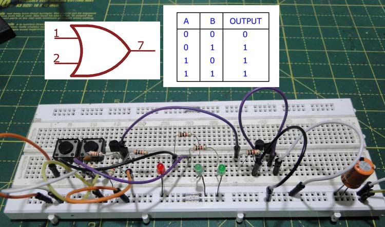
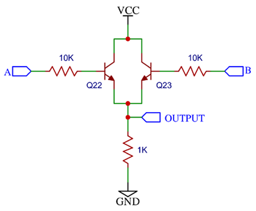
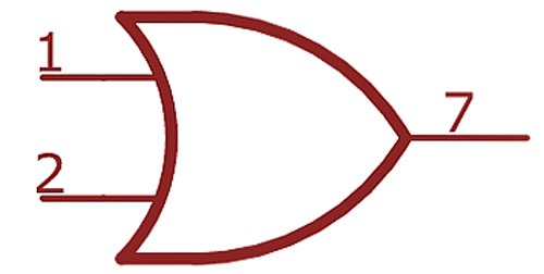
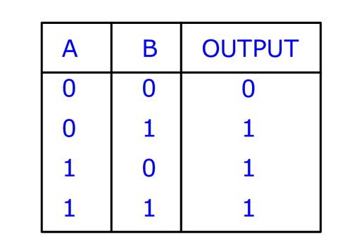
An OR gate is a fundamental digital logic circuit that outputs a high signal if at least one of its inputs is high. In this project, you will build an OR gate using discrete NPN small signal transistors, such as the 2N2222 or BC547, along with resistors. The circuit is constructed using a parallel transistor configuration where two NPN transistors have their collectors tied together and their emitters connected to ground. Each transistor's base is connected through a 1K current-limiting resistor to an input source, while a 10K pull-down resistor helps keep the base pins at a logical low when no input is applied. When you apply a voltage (a high signal) to either the first input, the second input, or both inputs simultaneously, the respective transistor turns on. This action completes the circuit path from the power supply, through a load resistor and an LED used for visual testing, down to ground. As a result, current flows through the LED, causing it to light up and visually indicate a high output state. If both inputs are disconnected or held at zero volts, neither transistor conducts, leaving the LED unlit to represent a low output state.
Why Build This
Discover how basic building blocks like transistors can be combined to form fundamental digital logic gates used in computers.
Practice assembling and testing physical electronic circuits on a breadboard using LEDs for instant visual feedback.
Understand the difference between software-based logic and real-world hardware electronics.
Real-World Application
Used in digital logic design, automotive safety warning systems (like door-ajar or seatbelt reminders), alarm systems, input multiplexing, and interrupt controllers.
Skills You'll Learn
breadboard prototyping
discrete transistor switching
basic digital logic design
resistor current limiting
circuit troubleshooting with LEDs
Safety Precautions
No specific precautions noted for this build — always follow general electronics safety practices.
Technology Tags
TRANSISTORS
BJT
LOGIC GATES
DIGITAL ELECTRONICS
NPN TRANSISTORS
BOOLEAN LOGIC
CIRCUIT DESIGN
Ready to build this?
We stock the boards, sensors and modules this project needs. A full parts list is coming soon — for now, browse our DIY Kits & components or search for Analog / Discrete parts.
Frequently Asked Questions
Do I need to write any code for this project?
No, this is a purely analog and discrete hardware project. It relies entirely on physical components like transistors and resistors to create logic, with no microcontroller or programming required.
What specific NPN transistor should I use?
You can use standard small-signal NPN transistors such as the 2N2222 or BC547, as both are widely available and function similarly in this low-power digital switching application.
Why are resistors needed if the transistors already control the circuit?
The 1K resistors protect the transistor bases from excessive current, while the 10K resistors act as pull-down resistors to ensure the inputs return to a stable low state when no voltage is applied.
Gallery

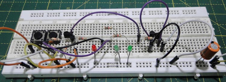
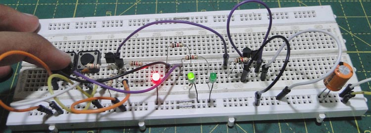
Kitkraft Project Hub — curated from the maker community, credited at the source.
PRJ-00116