This project is sourced from another site, not written by us — this list is our best match of their components against what we stock, not a verified bill of materials. Always check the original blog (linked above) for the actual parts list before buying.
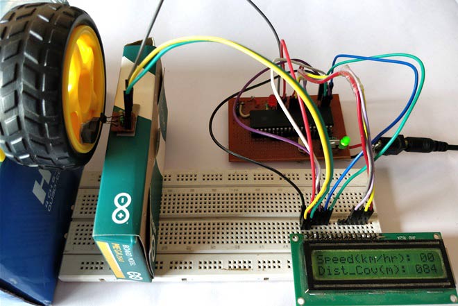
The Digital Speedometer and Odometer Circuit uses a PIC microcontroller as the central processing unit to calculate and display vehicle speed and total distance traveled. The core sensing mechanism relies on a Hall sensor, which detects passing magnetic fields. Typically, a small magnet is mounted to a rotating wheel, and as the wheel turns, the magnet triggers the Hall sensor with each revolution, generating electrical pulses. These pulses are sent to the PIC microcontroller via connecting wires. The microcontroller's internal timer and counter modules measure the frequency of these pulses to calculate speed based on the known circumference of the wheel. Additionally, by continuously accumulating the total number of pulse counts over time, the microcontroller calculates the total distance traveled, functioning as an odometer. The computed metrics—current speed and cumulative distance—are then processed and outputted to an LCD display for real-time viewing. The entire circuit is assembled on a breadboard or perfboard and powered by a steady power supply to ensure reliable operation of both the microcontroller and the logic components. Software written in the PIC MPLAB IDE or an equivalent compiler dictates how the microcontroller interprets the sensor inputs, updates the math algorithms, and refreshes the LCD output.
Why Build This
Gain hands-on experience in implementing embedded systems for automotive or transportation engineering applications.
Learn how to interface pulse-generating sensors like Hall sensors with microcontroller interrupt or counter pins.
Develop practical firmware skills in processing real-world physical rotation data into readable speed and distance metrics.
Real-World Application
Used in automotive dashboards, bicycles, and other wheeled vehicles to track speed and distance.
Skills You'll Learn
microcontroller pulse counting
Hall sensor interfacing
LCD display driving
embedded firmware development
frequency-to-speed conversion algorithms
Safety Precautions
No specific precautions noted for this build — always follow general electronics safety practices.
Technology Tags
PIC MICROCONTROLLER
HALL SENSOR
LCD DISPLAY
SPEEDOMETER
ODOMETER
EMBEDDED C
Frequently Asked Questions
A magnet is attached to a rotating wheel, causing the Hall sensor to output a voltage pulse every time the magnet passes by. The microcontroller measures the time interval between these pulses to calculate how fast the wheel is turning.
Yes, while PIC MPLAB IDE is the standard environment, you can use any equivalent compiler that supports your specific PIC microcontroller model to write and compile your C or assembly code.
The microcontroller simply keeps a running total of all the pulse counts received from the Hall sensor and multiplies that total by the distance covered in a single wheel rotation.
Gallery
This page is part of Kitkraft's Project Hub — a curated collection of electronics & robotics projects gathered from the maker community to help students and hobbyists discover and learn to build. Kitkraft does not claim authorship of the original project, and makes no representation as to the accuracy, completeness or safety of third-party source material. The summary and "How It Works" explanation above are AI-generated, rewritten with reference to the original tutorial — not a reproduction of it. Full credit and a direct link to the original source are provided above. If you're the original creator and have a concern about how your work is represented here, please contact us and we'll address it promptly.
Kitkraft Project Hub — curated from the maker community, credited at the source.
 Reed Switch 2×14mm Normally Open Magnetic Sensor
Out of stock
 Jumper Wire 10 Pin Male To Male 20cm
Rs. 45.00
 MB102 Adjustable Breadboard Power Supply Module (3.3V & 5V) for Arduino & Raspberry Pi
Rs. 139.00
 400 Points Mini Solderless Prototype PCB Breadboard High Quality
Rs. 89.00
 Jumper Wire 10 Pin Male To Female 20cm
Rs. 45.00


