This project demonstrates how to share a single DS3231 real-time clock between two Arduino microcontrollers—one managing an AC scheduling timer via a relay, and the other driving a color display.
This project is sourced from another site, not written by us — this list is our best match of their components against what we stock, not a verified bill of materials. Always check the original blog (linked above) for the actual parts list before buying.
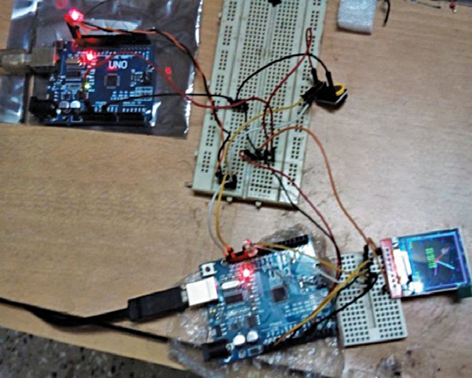
This intermediate communication systems project demonstrates how a single DS3231 Real Time Clock module can be shared between two separate ATMEGA328-based Arduino Uno boards. The DS3231 communicates via the I2C protocol, allowing multiple master devices to read the timekeeping registers if properly configured. In this circuit setup, the first Arduino Uno acts as the primary controller running the DS3231_AC_Scheduler.ino sketch. It queries the DS3231 for real-time data to manage an AC scheduling timer, activating a 5V relay module at programmed intervals. The relay module in turn controls a heavy-duty 5kW AC contactor to switch high-power mains equipment. Meanwhile, the second Arduino Uno accesses the same shared DS3231 clock module to retrieve time data independently, using it to drive a TFT ILI9163 128x128 color display that visually renders the current time and system status. Connection wires tie the shared I2C data and clock lines between the real-time clock module and both microcontroller boards, establishing a dual-system architecture powered from a common time reference.
Why Build This
Learn how to distribute a single I2C peripheral time reference across multiple microcontroller nodes in a synchronized embedded network.
Implement automated, schedule-based climate control using relays and high-power AC contactors for heavy electrical loads.
Practice driving small color graphic displays like the TFT ILI9163 to create real-time status dashboards for embedded systems.
Real-World Application
Automated climate control for server rooms, labs, or remote spaces using scheduled AC operation, preventing unnecessary continuous running during summers.
Skills You'll Learn
I2C bus communication
multi-master peripheral sharing
relay control logic
AC contactor interfacing
TFT color display graphics rendering
microcontroller timing synchronization
Safety Precautions
Exercise caution when working with high-voltage AC contactors and mains power relays to prevent electrical shock.
Technology Tags
DS3231
RTC
REAL TIME CLOCK
ATMEGA328
ARDUINO
RELAY
TFT ILI9163
I2C
SPI
AC CONTACTOR
Frequently Asked Questions
Yes, because the DS3231 acts as an I2C slave device, multiple microcontrollers configured as masters can request time data from it over the same SDA and SCL lines, provided bus conflicts are managed properly.
The Arduino Uno digital pins operate at 5V and can only source a small amount of current, which is far too weak to drive the high-current coil of a heavy-duty 5kW AC contactor. The intermediate 5V relay provides the necessary electrical isolation and switching power.
Both Arduino boards are wired to the DS3231 real-time clock module, allowing the second Arduino to independently query the clock registers over I2C to render the time on its color display.
Gallery
This page is part of Kitkraft's Project Hub — a curated collection of electronics & robotics projects gathered from the maker community to help students and hobbyists discover and learn to build. Kitkraft does not claim authorship of the original project, and makes no representation as to the accuracy, completeness or safety of third-party source material. The summary and "How It Works" explanation above are AI-generated, rewritten with reference to the original tutorial — not a reproduction of it. Full credit and a direct link to the original source are provided above. If you're the original creator and have a concern about how your work is represented here, please contact us and we'll address it promptly.
 5V 1 Channel Relay Module
Rs. 87.00
 Jumper Wire 10 Pin Male To Male 20cm
Rs. 45.00
 400 Points Mini Solderless Prototype PCB Breadboard High Quality
Rs. 89.00
 MB102 Adjustable Breadboard Power Supply Module (3.3V & 5V) for Arduino & Raspberry Pi
Rs. 139.00
 Jumper Wire 10 Pin Male To Female 20cm
Rs. 45.00


