Project Hub
/Basic Analog & Power Electronics/Sequential, Timing & Pulse Circuits/Fast PWM Generator with Verilog
Advanced
RASPBERRY PI
Project Specific
3 – 6 Hours
Partial Kit
Fast PWM Generator with Verilog
This project demonstrates the implementation of a fast Pulse Width Modulator (PWM) generator using Verilog, simulated via ModelSim and tested on a Basys 2 FPGA board.
We stock the boards, sensors and modules this project needs. A full parts list is coming soon — for now, browse our DIY Kits & components or search for Raspberry Pi parts.
This project is sourced from another site, not written by us — this list is our best match of their components against what we stock, not a verified bill of materials. Always check the original blog (linked above) for the actual parts list before buying.
We don't carry yet: FPGA / CPLD
Atmel AT90USB2 USB controller)
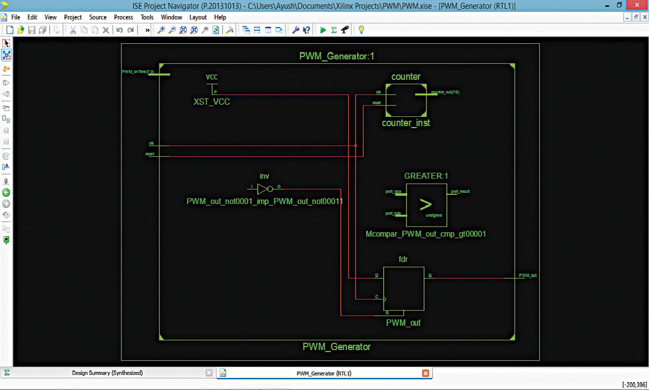
This project implements a high-speed Pulse Width Modulator (PWM) generator completely in hardware using Verilog HDL. At the core of the system is a digital counter and a comparator synthesized onto the Xilinx Spartan-3E FPGA residing on the Basys 2 development board. The Verilog code defines a register that acts as a free-running counter, incrementing with each clock cycle. A comparator continuously evaluates the current counter value against a predefined threshold or duty-cycle register. When the counter is below the threshold, the PWM output pin is driven high; once the counter exceeds or equals the threshold, the output drops low until the counter rolls over. By adjusting this numerical threshold, the effective duty cycle of the output square wave changes proportionally, yielding an analog-like average voltage level suitable for driving external loads. Because the logic executes in parallel within the FPGA fabric rather than sequentially on a standard microprocessor, the pulse generation achieves exceptional speed and timing precision. Before hardware implementation, the design is simulated in ModelSim to verify timing waveforms, duty-cycle accuracy, and edge transitions. Finally, the bitstream is transferred to the FPGA via the onboard Atmel AT90USB2 controller, allowing the physical pins of the Basys 2 board to output the live PWM signal.
Why Build This
Learn how to synthesize efficient hardware description language (Verilog) designs for FPGA fabrics rather than writing sequential software.
Master the timing, counter logic, and comparator structures required to generate precise Pulse Width Modulation signals.
Gain practical experience using professional verification tools like ModelSim alongside physical FPGA hardware deployment via the Basys 2 board.
Real-World Application
Motor speed control, dimming LED lights, and generating analog-like control signals from digital microcontrollers and FPGAs.
Skills You'll Learn
Verilog HDL coding
FPGA synthesis and implementation
digital timing and counter design
PWM signal generation
hardware waveform simulation
Safety Precautions
No specific precautions noted for this build — always follow general electronics safety practices.
Technology Tags
VERILOG
FPGA
PWM
MODELSIM
HARDWARE DESCRIPTION LANGUAGE
DIGITAL LOGIC
Frequently Asked Questions
FPGAs execute logic in parallel rather than sequentially, allowing for much faster switching frequencies and precise timing control that is independent of software execution loops.
ModelSim is used to simulate and verify the Verilog code's timing and waveform behavior before programming it onto the physical FPGA hardware.
The duty cycle is controlled by updating the comparison threshold value within the Verilog module, which alters the proportion of time the output signal remains high during each counter period.
Gallery
This page is part of Kitkraft's Project Hub — a curated collection of electronics & robotics projects gathered from the maker community to help students and hobbyists discover and learn to build. Kitkraft does not claim authorship of the original project, and makes no representation as to the accuracy, completeness or safety of third-party source material. The summary and "How It Works" explanation above are AI-generated, rewritten with reference to the original tutorial — not a reproduction of it. Full credit and a direct link to the original source are provided above. If you're the original creator and have a concern about how your work is represented here, please contact us and we'll address it promptly.
Kitkraft Project Hub — curated from the maker community, credited at the source.