🪔 Diwali Break: Orders placed now will ship from 25th November 2026. Place your order today — we'll get it to you right after we're back!
Project Hub /Test & Measurement Instrumentation/Multimeters, Voltmeters & Ammeters/Finger-Sized Portable Voltmeter
Finger-Sized Portable Voltmeter
Beginner
ARDUINO
₹500 – ₹1,500
3 – 6 Hours
Partial Kit

Finger-Sized Portable Voltmeter

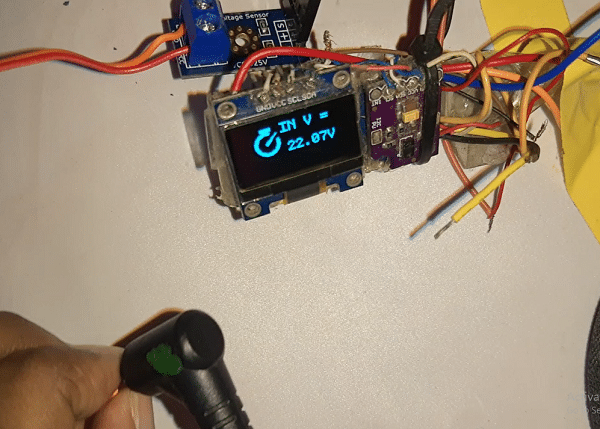
A compact, keyring-sized portable DC voltmeter built using an Arduino and an OLED display that measures voltages from 0V to 24V.

Originally published on ElectronicsForU
View original tutorial

Parts You'll Need

This project is sourced from another site, not written by us — this list is our best match of their components against what we stock, not a verified bill of materials. Always check the original blog (linked above) for the actual parts list before buying.

We don't carry yet: Arduino (unspecified board)
Battery (generic / unspecified)
Voltage Sensor Module

Browse all components

How It Works

Why Build This

Provides electrical and computer engineering students with a practical, portable instrument for rapid field testing of DC power supplies and lab prototypes without dragging out benchtop multimeters.
Reinforces core undergraduate circuit theory by implementing a physical resistor divider network and mapping its mathematical transfer function directly into embedded firmware.

Real-World Application

Useful for electrical and electronics engineers, students, and hobbyists for rapid field testing of batteries, DC power sources, and electronic circuits without needing a bulky standard multimeter.

Skills You'll Learn

Voltage divider design
Analog-to-digital conversion
I2C communication protocol
Embedded display integration
Microcontroller firmware scaling

Safety Precautions

Ensure correct polarity connections (positive to power source, negative to GND) to prevent damage to the circuit and microcontroller.

Technology Tags

ARDUINO
OLED DISPLAY
VOLTAGE DIVIDER
C++
ELECTRONICS TESTING
PORTABLE INSTRUMENTS

Frequently Asked Questions

The resistor values in the voltage divider are specifically chosen to scale 0V-24V down to the Arduino's 0V-5V safe ADC limit. Exceeding 24V will output a voltage higher than 5V to the analog pin, potentially damaging the microcontroller.
The OLED display communicates via the I2C protocol, which only requires four wires: VCC, GND, SDA, and SCL connected to the corresponding pins on the Arduino board.
Yes, due to standard component tolerances in the voltage divider resistors, you may need to fine-tune the multiplier coefficient in your Arduino code by comparing your device's reading against a trusted bench multimeter.

Gallery

This page is part of Kitkraft's Project Hub — a curated collection of electronics & robotics projects gathered from the maker community to help students and hobbyists discover and learn to build. Kitkraft does not claim authorship of the original project, and makes no representation as to the accuracy, completeness or safety of third-party source material. The summary and "How It Works" explanation above are AI-generated, rewritten with reference to the original tutorial — not a reproduction of it. Full credit and a direct link to the original source are provided above. If you're the original creator and have a concern about how your work is represented here, please contact us and we'll address it promptly.

Kitkraft Project Hub — curated from the maker community, credited at the source.
PRJ-00476