Integration of Mixed Signal Processing Into Smart Locking Systems Using Finite State Machine
Project Hub
/Test & Measurement Instrumentation/Multimeters, Voltmeters & Ammeters/Integration of Mixed Signal Processing Into Smart Locking Systems Using Finite State Machine
Advanced
ANALOG / DISCRETE
< ₹500
6 – 12 Hours
Partial Kit
Integration of Mixed Signal Processing Into Smart Locking Systems Using Finite State Machine
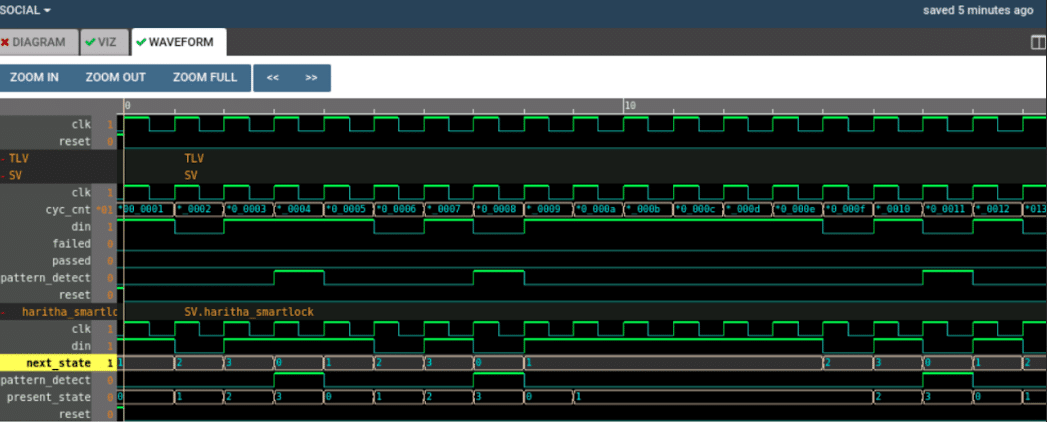
This project designs a smart lock system using a Moore state machine implemented in Verilog combined with mixed-signal processing circuit tools like eSim and Makerchip.
We stock the boards, sensors and modules this project needs. A full parts list is coming soon — for now, browse our DIY Kits & components or search for Analog / Discrete parts.
This project is sourced from another site, not written by us — this list is our best match of their components against what we stock, not a verified bill of materials. Always check the original blog (linked above) for the actual parts list before buying.
We don't carry yet: mixed-signal circuit components
This advanced project integrates digital control logic with analog processing to build a secure smart locking system governed by a Finite State Machine. At the heart of the system is a Moore state machine written in Verilog, which manages the sequential validation of access codes or unlock sequences. Because the real world operates in continuous analog signals while digital processors require discrete values, mixed-signal components bridge this divide. An Analog-to-Digital Converter (ADC) translates incoming analog sensor voltages or key signals into digital data that the logic controller can evaluate. Conversely, a Digital-to-Analog Converter (DAC) takes digital control commands and converts them back into analog output signals, capable of driving actuator mechanisms like solenoids or relays for the lock itself. A dedicated clock generator coordinates the timing of state transitions across the digital architecture, ensuring synchronized operation. Using electronic design automation tools, the system's digital behavior is co-simulated alongside analog circuit dynamics, allowing engineers to verify that the discrete hardware and HDL-based logic seamlessly interact before physical deployment.
Why Build This
Gain hands-on undergraduate engineering experience bridging digital hardware description languages with continuous analog circuit simulation.
Design and validate secure sequence validation logic used in modern keyless entry systems and access control hardware.
Master a complete open-source electronic design automation toolchain spanning schematic capture, PCB layout, and mixed-signal simulation.
Real-World Application
Modern digital security systems, keyless entry door locks, and access control hardware requiring secure sequence validation.
Skills You'll Learn
Finite state machine design
Verilog HDL coding
mixed-signal circuit simulation
ADC and DAC interfacing
clock generation and timing coordination
electronic design automation
Safety Precautions
No specific precautions noted for this build — always follow general electronics safety practices.
Technology Tags
FINITE STATE MACHINE
VERILOG
MIXED SIGNAL PROCESSING
MOORE MACHINE
ESIM
MAKERCHIP
NGSPICE
DIGITAL LOGIC
Frequently Asked Questions
In a Moore state machine, the output depends exclusively on the current state of the system, providing predictable and stable control transitions ideal for security validation.
Makerchip and NgVeri are utilized for developing and testing the digital Verilog logic, while eSim and NgSpice handle the analog mixed-signal circuit simulation, allowing for a holistic system test.
Yes, this project relies heavily on software simulation tools, allowing you to fully verify the logic and analog-to-digital interactions virtually before fabricating any hardware.
Gallery
This page is part of Kitkraft's Project Hub — a curated collection of electronics & robotics projects gathered from the maker community to help students and hobbyists discover and learn to build. Kitkraft does not claim authorship of the original project, and makes no representation as to the accuracy, completeness or safety of third-party source material. The summary and "How It Works" explanation above are AI-generated, rewritten with reference to the original tutorial — not a reproduction of it. Full credit and a direct link to the original source are provided above. If you're the original creator and have a concern about how your work is represented here, please contact us and we'll address it promptly.
Kitkraft Project Hub — curated from the maker community, credited at the source.