This project is sourced from another site, not written by us — this list is our best match of their components against what we stock, not a verified bill of materials. Always check the original blog (linked above) for the actual parts list before buying.
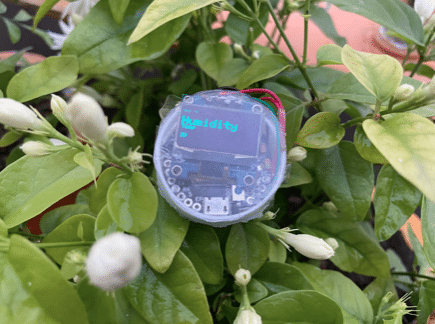
This project integrates an SSD1306 I2C OLED display with the Indusboard, an ESP32-based development board, to render graphical and textual output. The system is powered either through a standard USB cable or an external 5V power supply connected to the Indusboard. Communication between the Indusboard and the display relies on the I2C (Inter-Integrated Circuit) protocol, which utilizes a two-wire interface: a Serial Data line (SDA) and a Serial Clock line (SCL). Within the Arduino IDE environment, the U8g2 library acts as the rendering engine. It handles frame buffer management and translates high-level drawing commands into precise I2C data packets. When the Indusboard runs the compiled sketch, it continuously pushes graphical data frames over the SDA and SCL lines to the SSD1306 controller embedded on the display module. The OLED screen itself consists of an array of organic light-emitting diodes that illuminate independently when subjected to the pixel data sent by the microcontroller. Because each pixel generates its own light, no separate backlight is necessary, allowing for high-contrast visual readouts driven directly from the ESP32's processing core.
Why Build This
Develop real-time visual monitoring interfaces for IoT and embedded telemetry systems.
Implement I2C peripheral communication protocols for multi-device microcontroller networks.
Design on-device debugging readouts to inspect sensor values without relying entirely on serial monitor logs.
Real-World Application
Used for adding visual user interfaces, debugging readouts, and displaying sensor data in IoT and embedded devices.
Skills You'll Learn
I2C communication protocol configuration
embedded graphics rendering
microcontroller peripheral wiring
library integration in Arduino IDE
Safety Precautions
No specific precautions noted for this build — always follow general electronics safety practices.
Technology Tags
OLED DISPLAY
I2C
INDUSBOARD
MICROCONTROLLER
EMBEDDED SYSTEMS
ARDUINO IDE
Frequently Asked Questions
You should connect the display's SDA and SCL pins to the designated default I2C pins on your Indusboard (ESP32 DevKit v1), typically GPIO 21 for SDA and GPIO 22 for SCL.
The U8g2 library is specifically designed to manage pixel buffers and command sets for matrix-based displays like the SSD1306, allowing you to draw text, shapes, and custom graphics efficiently over an I2C interface.
Yes, most SSD1306 OLED modules include an onboard voltage regulator and can accept either 3.3V or 5V from the corresponding Indusboard power pins, matching the voltage levels of the microcontroller.
Gallery
This page is part of Kitkraft's Project Hub — a curated collection of electronics & robotics projects gathered from the maker community to help students and hobbyists discover and learn to build. Kitkraft does not claim authorship of the original project, and makes no representation as to the accuracy, completeness or safety of third-party source material. The summary and "How It Works" explanation above are AI-generated, rewritten with reference to the original tutorial — not a reproduction of it. Full credit and a direct link to the original source are provided above. If you're the original creator and have a concern about how your work is represented here, please contact us and we'll address it promptly.
Kitkraft Project Hub — curated from the maker community, credited at the source.
 0.96 Inch I2C/IIC 4pin OLED Display Module White
Rs. 349.00
 Jumper Wire 10 Pin Male To Male 20cm
Rs. 45.00
 MB102 Adjustable Breadboard Power Supply Module (3.3V & 5V) for Arduino & Raspberry Pi
Rs. 139.00
 400 Points Mini Solderless Prototype PCB Breadboard High Quality
Rs. 89.00
 Jumper Wire 10 Pin Male To Female 20cm
Rs. 45.00


