Low-Cost 40A, 1200V Solid-State Relay And Voltage Controller
Project Hub
/Audio Displays & Interactive Media/LED Matrix & Cube Displays/Low-Cost 40A, 1200V Solid-State Relay And Voltage Controller
Beginner
ANALOG / DISCRETE
Project Specific
3 – 6 Hours
Partial Kit
Low-Cost 40A, 1200V Solid-State Relay And Voltage Controller
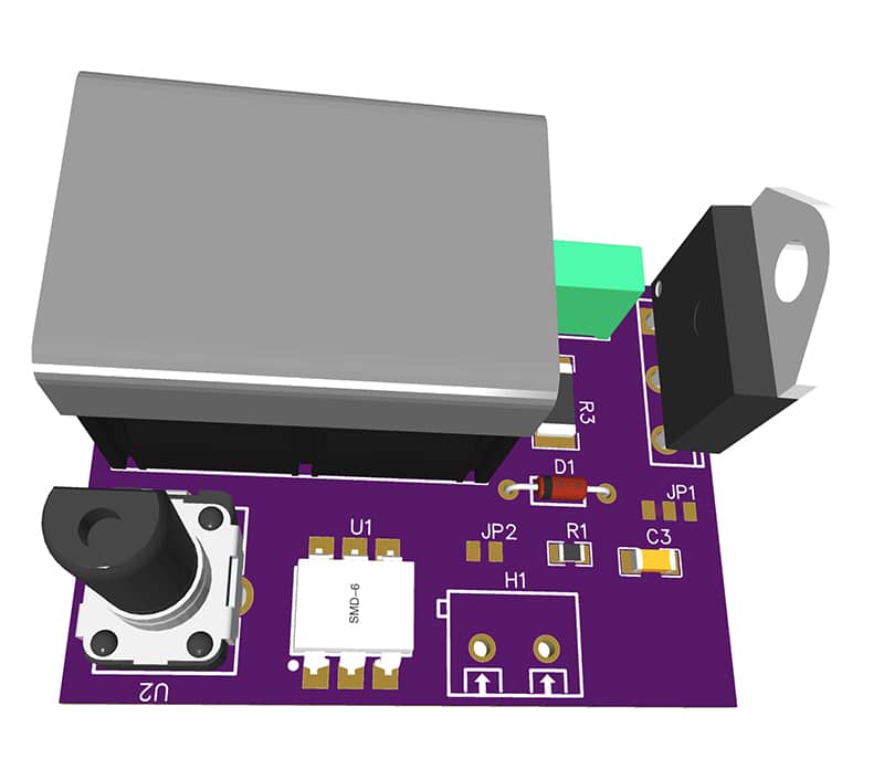
This system presents a fast-switching, voltage-controlled solid-state relay utilizing a BTA41-1200BW TRIAC and MOC3041 opto-triac to handle up to 40A continuous current.
We stock the boards, sensors and modules this project needs. A full parts list is coming soon — for now, browse our DIY Kits & components or search for Analog / Discrete parts.
This project is sourced from another site, not written by us — this list is our best match of their components against what we stock, not a verified bill of materials. Always check the original blog (linked above) for the actual parts list before buying.
We don't carry yet: Solid State Relay / Triac / Dimmer
Capacitors
Header Pins / Terminals / Connectors
DIAC
This low-cost voltage controller and solid-state relay system is designed to safely and efficiently switch high-power AC loads using discrete analog components. At the heart of the circuit is the BTA41-1200BW, a robust 40A, 1200V TRIAC that acts as the primary power switch, capable of handling heavy alternating current applications without mechanical wear. Because high-power mains circuits require strict galvanic isolation to protect low-voltage control hardware or operators, the system integrates an MOC3041 opto-triac. The opto-triac uses an internal infrared LED to optically trigger the main TRIAC while providing high-voltage electrical isolation between the control side and the mains power side. Additionally, the circuit features a DIAC for precise trigger threshold management, terminal connectors (C2, D1) for secure physical wiring of AC lines, and protective passive components including a 100n-400V polyester capacitor (C1) and a standard 100nF capacitor (C3). These capacitors work in conjunction with the semiconductor switches to form snubber networks, suppressing high dv/dt voltage spikes and electrical noise generated when switching inductive loads like motors or transformers. By coordinating optical isolation, precise triggering, and robust power handling, the circuit delivers reliable, fast-switching AC control entirely through analog and discrete component principles without requiring any microcontrollers or software.
Why Build This
Design and implement high-power industrial automation and IoT systems requiring robust AC load control up to 40A and 1200V.
Explore advanced motor speed control and lighting dimming techniques using solid-state switching instead of mechanical relays.
Gain practical undergraduate-level experience with optical isolation, mains-voltage safety, and snubber network design for inductive loads.
Real-World Application
Industrial automation, IoT systems, high-power AC load control, motor speed control, and lighting dimming.
Skills You'll Learn
High-voltage AC circuit design
opto-isolator integration
TRIAC and DIAC triggering
snubber network implementation
inductive load management
electrical safety and enclosure planning
Safety Precautions
Exercise extreme caution when working with high-voltage mains AC circuits (up to 1200V). Ensure proper insulation and enclosure to prevent electric shock.
Technology Tags
TRIAC
OPTO-TRIAC
SOLID-STATE RELAY
POWER ELECTRONICS
AC VOLTAGE CONTROL
MOC3041
BTA41-1200BW
Frequently Asked Questions
The MOC3041 provides crucial galvanic isolation, protecting low-voltage control circuitry and users from dangerous high-voltage AC mains.
These capacitors typically function as part of a snubber network to suppress voltage transients and electrical noise, preventing false triggering when switching inductive loads.
No, this is a purely analog and discrete system that does not list any software requirements, meaning it can be controlled directly via external voltage signals.
Gallery
This page is part of Kitkraft's Project Hub — a curated collection of electronics & robotics projects gathered from the maker community to help students and hobbyists discover and learn to build. Kitkraft does not claim authorship of the original project, and makes no representation as to the accuracy, completeness or safety of third-party source material. The summary and "How It Works" explanation above are AI-generated, rewritten with reference to the original tutorial — not a reproduction of it. Full credit and a direct link to the original source are provided above. If you're the original creator and have a concern about how your work is represented here, please contact us and we'll address it promptly.
Kitkraft Project Hub — curated from the maker community, credited at the source.