Intermediate
ANALOG / DISCRETE
Project Specific
3 – 6 Hours
Overcurrent Fault Detector
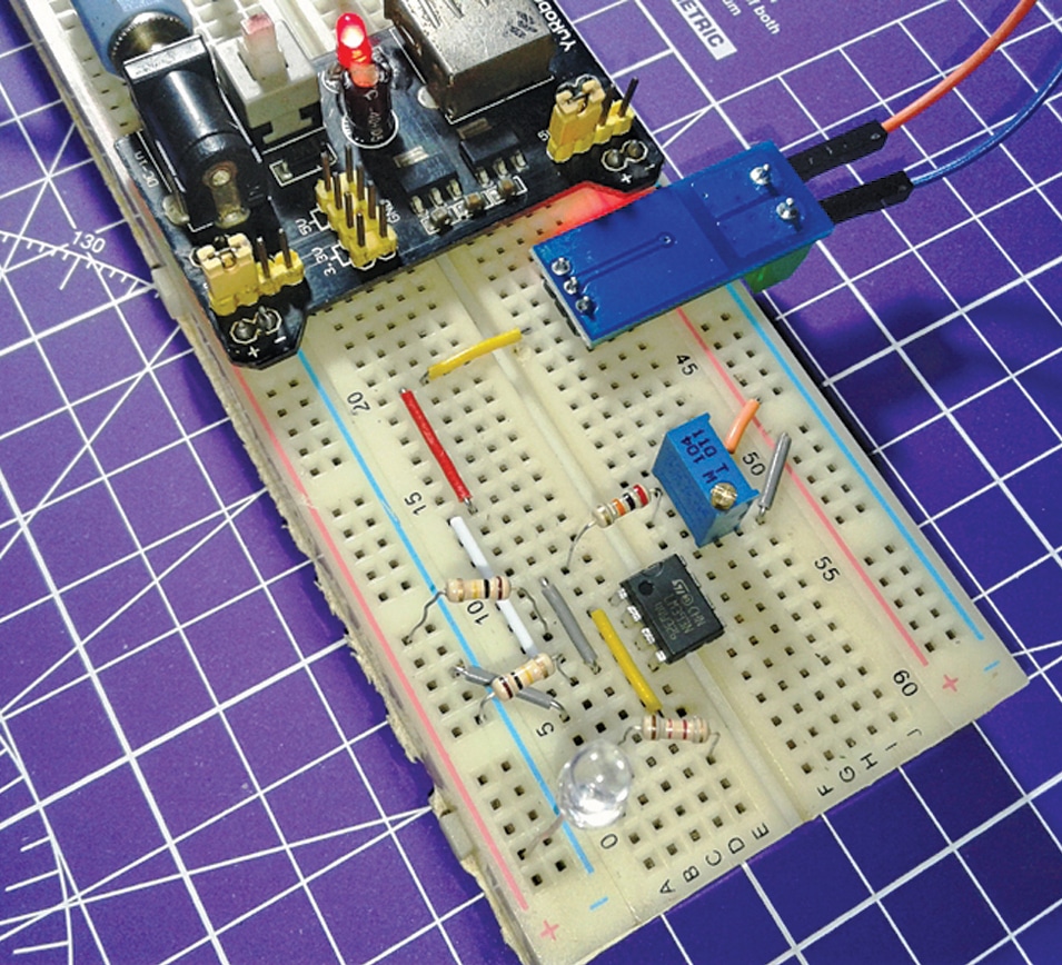
An overcurrent fault detector circuit that raises an alert and can trip a relay when the current passing through a system exceeds a pre-set threshold limit.
Originally published by T.K. Hareendran on ElectronicsForU
View original tutorial
How It Works
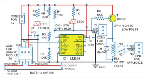
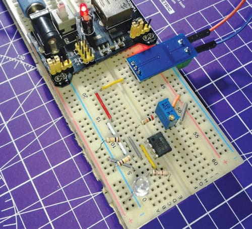
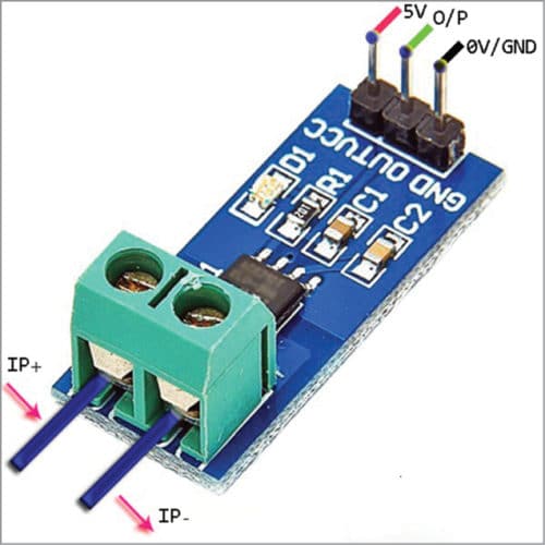
The Overcurrent Fault Detector is designed to monitor electrical current flowing through a system and trigger a response if it crosses a predefined safety threshold. At the front end, the ACS712 current sensor module (5A version) measures the load current and translates it into a proportional analog voltage output. This voltage signal is routed to the input of an LM393 operational amplifier (IC1), which functions as a voltage comparator. Using a potentiometer connected to the comparator, you can establish a precise reference voltage corresponding to your maximum allowable current limit.
Under normal operating conditions, the sensor output remains below the threshold set by the potentiometer, keeping the op-amp output in a state that leaves the BC557 PNP transistor (T1) turned off. When an overcurrent condition occurs, the sensor's voltage output exceeds the reference threshold, causing the LM393 output to switch states. This transition biases the BC557 PNP transistor into conduction, energizing the coil of the 5V single-changeover relay (RL1). As the relay trips, it can physically disconnect or switch the connected load. A 1N4007 diode (D1) is placed across the relay coil to safely suppress inductive kickback voltages when the relay turns off, protecting the semiconductor components from damage. LEDs provide visual indication of power and fault status, while onboard resistors and capacitors stabilize the circuit's bias points and filter out high-frequency noise.
Why Build This
Design robust hardware protection circuits for undergraduate electrical and mechatronic systems to prevent expensive component burnout.
Learn to integrate analog sensors with discrete operational amplifiers for real-time threshold detection without relying on microcontrollers.
Implement electromechanical switching and inductive load protection using relays and flyback diodes.
Real-World Application
Overcurrent protection for electrical appliances, motor protection, power supplies, and general load monitoring.
Skills You'll Learn
analog sensor integration
comparator circuit design
transistor switching
relay control and flyback protection
threshold tuning with potentiometers
Safety Precautions
Exercise caution when dealing with high current or voltage connections at the sensor terminals.
Technology Tags
ACS712
HALL EFFECT SENSOR
LM393 COMPARATOR
RELAY DRIVER
CURRENT SENSING
PCB
Ready to build this?
We stock the boards, sensors and modules this project needs. A full parts list is coming soon — for now, browse our DIY Kits & components or search for Analog / Discrete parts.
Frequently Asked Questions
Can I use this circuit with an AC load as well as DC?
The ACS712 sensor can measure both AC and DC current, but the relay and downstream control circuit must be rated appropriately for the voltages and currents you are switching.
How do I calibrate the trip threshold?
You adjust the potentiometer while passing a known, controlled maximum current through the sensor until the relay trips at your desired limit.
Why is the 1N4007 diode necessary?
The diode acts as a flyback or freewheeling diode, providing a safe path for the magnetic energy stored in the relay coil to dissipate when it turns off, preventing voltage spikes from destroying the transistor.
Gallery

Kitkraft Project Hub — curated from the maker community, credited at the source.
PRJ-00286