Personalised DIY E-Paper Clock Using ESP32 Microcontroller
Project Hub
/Basic Analog & Power Electronics/Power Supplies & Voltage Regulators/Personalised DIY E-Paper Clock Using ESP32 Microcontroller
Intermediate
ESP32
₹1,500 – ₹5,000
3 – 6 Hours
Partial Kit
Personalised DIY E-Paper Clock Using ESP32 Microcontroller
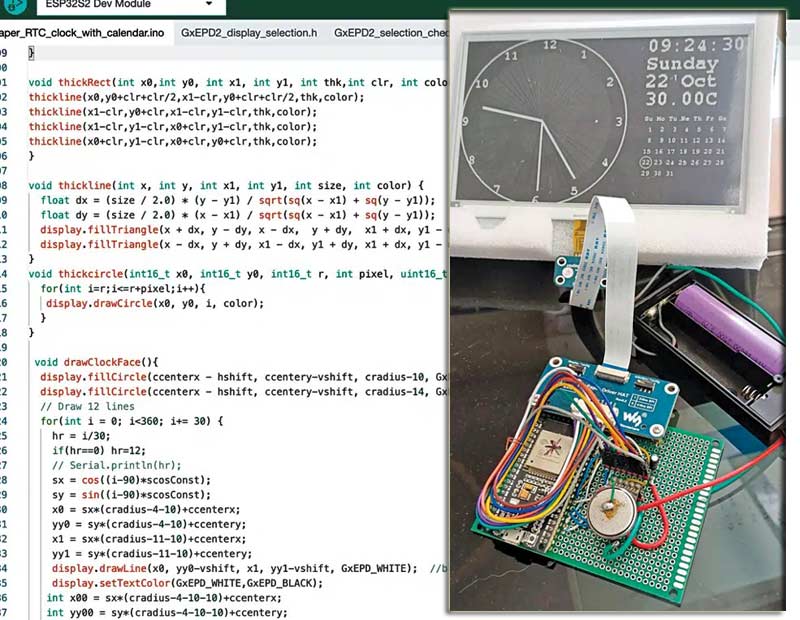
A personalized DIY clock built using an ESP32 microcontroller and a 7.5-inch black-and-white e-paper display for ultra-low power consumption and wide viewing angles.
This project is sourced from another site, not written by us — this list is our best match of their components against what we stock, not a verified bill of materials. Always check the original blog (linked above) for the actual parts list before buying.
The Personalised DIY E-Paper Clock operates by coordinating timekeeping, processing, and visual output across several interconnected hardware modules. At the core of the system is the ESP32 microcontroller (MOD1), which manages the overall logic and coordinates data updates. Because accurate timekeeping is critical for a clock, the system relies on an external DS3231 Real-Time Clock module (MOD3) to track hours, minutes, and seconds independently, maintaining precision even if the main processor enters low-power states. To ensure a stable and reliable power supply, input voltage is regulated down to a steady 3.3 volts by the HT7333A voltage regulator (IC1), supported by two 10 microfarad 16-volt electrolytic capacitors (C1, C2) that filter out voltage spikes and smooth out transient current demands. When the time changes or a display refresh is triggered, the ESP32 sends updated image data to the large 19-centimeter (7.5-inch) black-and-white e-paper display (MOD2). Unlike traditional LCD or LED screens, the e-paper display only draws power when its image is actively changing; once the tiny microcapsules inside the panel shift to form the text or graphics, they retain that visual state indefinitely without consuming any electrical current. This unique characteristic allows the system to remain in ultra-low power states for extended periods, making it ideal for continuous, battery-friendly operation.
Why Build This
Design and deploy ultra-low power embedded systems suitable for energy-efficient digital signage and smart home status panels.
Integrate multiple communication interfaces and specialized peripheral modules, such as an external RTC and an e-paper display, with a microcontroller.
Apply power management principles using dedicated voltage regulators and filtering capacitors to optimize battery life in portable engineering projects.
Real-World Application
Low-power environmental displays, energy-efficient digital signage, smart home status panels, and alternative reading or clock interfaces.
Skills You'll Learn
Microcontroller firmware development
I2C communication protocol
power supply regulation and filtering
e-paper display interfacing
real-time clock integration
Safety Precautions
No specific precautions noted for this build — always follow general electronics safety practices.
Technology Tags
ESP32
E-PAPER DISPLAY
DS3231 RTC
HT7333A VOLTAGE REGULATOR
EMBEDDED SYSTEMS
DIGITAL CLOCK
LOW POWER ELECTRONICS
Frequently Asked Questions
E-paper displays only consume power when the image is actively changing. This allows the clock to show the time continuously without draining significant power, making it perfect for long-term or battery-powered operation.
The DS3231 is a specialized Real-Time Clock with high precision and its own backup power capability, ensuring the clock keeps accurate time reliably even if the ESP32 resets or enters deep sleep.
Yes, C1 and C2 help stabilize the power supply by smoothing out voltage ripples and handling transient current spikes, ensuring the HT7333A regulator and downstream ICs operate reliably.
This page is part of Kitkraft's Project Hub — a curated collection of electronics & robotics projects gathered from the maker community to help students and hobbyists discover and learn to build. Kitkraft does not claim authorship of the original project, and makes no representation as to the accuracy, completeness or safety of third-party source material. The summary and "How It Works" explanation above are AI-generated, rewritten with reference to the original tutorial — not a reproduction of it. Full credit and a direct link to the original source are provided above. If you're the original creator and have a concern about how your work is represented here, please contact us and we'll address it promptly.
Kitkraft Project Hub — curated from the maker community, credited at the source.
 ESP32 WiFi+Bluetooth CP2102 Development Board
Rs. 520.00
 Jumper Wire 10 Pin Male To Male 20cm
Rs. 45.00
 400 Points Mini Solderless Prototype PCB Breadboard High Quality
Rs. 89.00
 MB102 Adjustable Breadboard Power Supply Module (3.3V & 5V) for Arduino & Raspberry Pi
Rs. 139.00
 Jumper Wire 10 Pin Male To Female 20cm
Rs. 45.00


