This project is sourced from another site, not written by us — this list is our best match of their components against what we stock, not a verified bill of materials. Always check the original blog (linked above) for the actual parts list before buying.
This list includes a generic resistor set
as a placeholder — it is not matched to the exact value or part number this circuit needs. The correct one is specified on the original source page linked above; check it before buying.
We don't carry yet: PIC Microcontroller
Custom PCB / PCB Fab
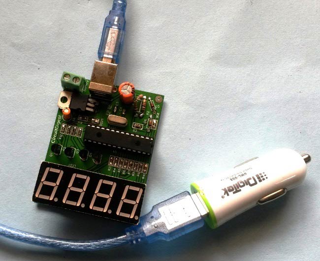
The PIC Based Car Battery Voltage Monitoring System operates by interfacing an automotive 12V electrical system with a PIC microcontroller to continuously track battery health. Because a car's electrical system typically operates at voltages higher than a standard microcontroller's safe input threshold, the circuit utilizes voltage divider resistors. These resistors scale down the incoming automotive voltage to a safe, proportional analog level that the PIC microcontroller can accurately measure. Power for the onboard electronics is reliably supplied by integrating USB car charger components, which step down the vehicle's dynamic 12V output to a stable 5V rail. Once processed by the microcontroller, the voltage data is evaluated. The system features a custom PCB that neatly organizes all interconnections, keeping the wiring secure and compact. Connecting wires route the scaled signals and power between the voltage divider, the PIC microcontroller, and the display elements. Although no specific software is listed, standard embedded firmware would interpret the analog-to-digital converter readings from the voltage divider, allowing the system to display the real-time battery status and alert the user to potential charging system failures or impending battery death before the vehicle fails to start.
Why Build This
Apply undergraduate-level embedded systems design to solve a practical automotive engineering problem.
Gain hands-on experience designing and fabricating custom PCBs for power-sensitive monitoring applications.
Implement analog signal conditioning techniques like voltage division to interface high-voltage domains safely with microcontrollers.
Real-World Application
Preventing unexpected vehicle breakdowns due to dead or failing car batteries by providing real-time voltage monitoring.
Skills You'll Learn
Microcontroller analog-to-digital conversion
voltage divider design and calculation
custom PCB layout and fabrication
power regulation using automotive USB components
embedded hardware integration
Safety Precautions
Exercise caution when working with automotive electrical systems and 12V batteries to avoid short circuits.
Technology Tags
PIC MICROCONTROLLER
BATTERY MONITORING
PCB DESIGN
VOLTAGE DIVIDER
EMBEDDED SYSTEMS
Frequently Asked Questions
A car battery operates around 12V to 14.4V, which exceeds the maximum input voltage rating of a standard PIC microcontroller. The voltage divider safely steps down this voltage to a range the microcontroller's analog inputs can measure without damage.
Direct connection is not recommended because automotive electrical systems experience severe voltage spikes and noise. This project uses USB car charger components to regulate the 12V input down to a stable 5V supply suitable for the microcontroller.
Yes, although specific software is not listed, you will need to write or load firmware onto the PIC microcontroller to read the analog inputs from the voltage divider and output the monitoring data.
Gallery
This page is part of Kitkraft's Project Hub — a curated collection of electronics & robotics projects gathered from the maker community to help students and hobbyists discover and learn to build. Kitkraft does not claim authorship of the original project, and makes no representation as to the accuracy, completeness or safety of third-party source material. The summary and "How It Works" explanation above are AI-generated, rewritten with reference to the original tutorial — not a reproduction of it. Full credit and a direct link to the original source are provided above. If you're the original creator and have a concern about how your work is represented here, please contact us and we'll address it promptly.
Kitkraft Project Hub — curated from the maker community, credited at the source.
 10pcs - 220 ohm 1/4 W Resistor Set
Rs. 39.00
 MB102 Adjustable Breadboard Power Supply Module (3.3V & 5V) for Arduino & Raspberry Pi
Rs. 139.00
 Jumper Wire 10 Pin Male To Male 20cm
Rs. 45.00
 400 Points Mini Solderless Prototype PCB Breadboard High Quality
Rs. 89.00
 Jumper Wire 10 Pin Male To Female 20cm
Rs. 45.00


