This project is sourced from another site, not written by us — this list is our best match of their components against what we stock, not a verified bill of materials. Always check the original blog (linked above) for the actual parts list before buying.
This list includes a generic resistor set
as a placeholder — it is not matched to the exact value or part number this circuit needs. The correct one is specified on the original source page linked above; check it before buying.
We don't carry yet: Transformer
Transistors (BC547 / 2N2222 / TIP / MOSFET)
Speaker / Audio Amplifier
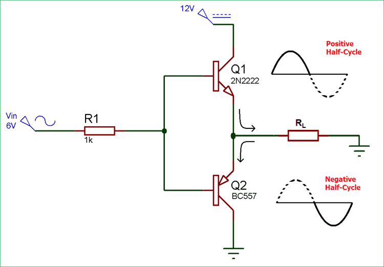
The push-pull amplifier circuit utilizes complementary transistor stages to drive an audio speaker and an LED load using discrete analog components on a breadboard. The heart of the circuit relies on a pair of complementary transistors: a 2N2222 NPN transistor and a BC557 PNP transistor. In a push-pull configuration, these transistors share the amplification workload by splitting the signal cycle. The NPN transistor handles the positive half-cycles of the incoming signal, sourcing current to push it through the output load, while the PNP transistor handles the negative half-cycles, sinking current to pull it. This complementary arrangement significantly improves efficiency compared to single-transistor Class A topologies by minimizing idle power dissipation. Bias resistors (1k, two nos) are used to set the operating points for the transistors, helping mitigate crossover distortion as the signal transitions between the NPN and PNP active regions (such as in Class B or AB operation). A center-tapped 6-0-6 transformer is typically incorporated into such analog power stages to couple the alternating current signals, match impedances between the active devices and the speaker, or provide balanced voltage rails. As the transistors modulate current in response to the input, the combined output drives the speaker to produce sound and illuminates the LED to visually indicate signal activity. Because this build is implemented on a standard analog breadboard without a dedicated microcontroller or PCB, it relies entirely on fundamental analog circuit principles, discrete semiconductor behavior, and passive components.
Why Build This
Analyze the behavior of complementary transistor pairs and understand how Class A, Class B, and Class AB output stages minimize crossover distortion in power amplifiers.
Gain practical undergraduate-level experience wiring discrete analog power circuits on a breadboard, utilizing center-tapped transformers and inductive coupling for audio loads.
Evaluate circuit efficiency and signal fidelity by observing real-world outputs across both an LED indicator and an analog speaker.
Real-World Application
Audio amplifiers and speaker systems, power amplifiers, motor control circuits, and signal processing applications.
Skills You'll Learn
transistor biasing
complementary symmetry design
push-pull amplification
audio output staging
transformer coupling
analog circuit troubleshooting
Safety Precautions
Flagged during content review — not in the original source
Exercise caution when working with transformers and power amplification circuits; ensure proper polarity and component ratings to prevent overheating or component damage.
Technology Tags
AMPLIFIER
PUSH-PULL
NPN TRANSISTOR
PNP TRANSISTOR
MOSFET
AUDIO ELECTRONICS
CLASS A
CLASS B
CLASS AB
POWER ELECTRONICS
Frequently Asked Questions
The NPN (2N2222) and PNP (BC557) transistors form a complementary pair where each device handles one half of the signal cycle—the NPN pushes current during the positive swing and the PNP pulls current during the negative swing.
The 6-0-6 transformer is used for AC voltage step-down, signal isolation, or impedance matching between the amplifier stages and the speaker load.
No, this is a purely analog discrete hardware project built on a breadboard, so no microcontroller programming or software is required.
Gallery
This page is part of Kitkraft's Project Hub — a curated collection of electronics & robotics projects gathered from the maker community to help students and hobbyists discover and learn to build. Kitkraft does not claim authorship of the original project, and makes no representation as to the accuracy, completeness or safety of third-party source material. The summary and "How It Works" explanation above are AI-generated, rewritten with reference to the original tutorial — not a reproduction of it. Full credit and a direct link to the original source are provided above. If you're the original creator and have a concern about how your work is represented here, please contact us and we'll address it promptly.
 10pcs - 220 ohm 1/4 W Resistor Set
Rs. 39.00
 10pcs 5mm RED Diffused Light Emitting Diodes - LEDs Set
Rs. 39.00
 400 Points Mini Solderless Prototype PCB Breadboard High Quality
Rs. 89.00
 MB102 Adjustable Breadboard Power Supply Module (3.3V & 5V) for Arduino & Raspberry Pi
Rs. 139.00
 Jumper Wire 10 Pin Male To Male 20cm
Rs. 45.00
 Jumper Wire 10 Pin Male To Female 20cm
Rs. 45.00


