Project Hub
/IoT & Connected Devices/Smart Home & Building Automation/Real-time Web-based Home Automation
Intermediate
ESP32
₹1,500 – ₹5,000
3 – 6 Hours
Partial Kit
Real-time Web-based Home Automation
A scalable, real-time home automation system built using the IndusBoard Coin (ESP32-S2) to wirelessly control AC appliances via an embedded web interface.
This project is sourced from another site, not written by us — this list is our best match of their components against what we stock, not a verified bill of materials. Always check the original blog (linked above) for the actual parts list before buying.
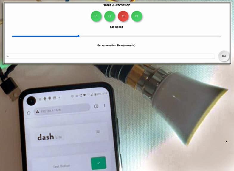
The Real-time Web-based Home Automation system operates by hosting an interactive embedded web server directly on the IndusBoard Coin microcontroller board, which features an ESP32-S2 processor. Users can access this custom web interface via any standard browser connected to the same local wireless network. When a user interacts with the digital controls on the webpage—such as clicking a button or adjusting a slider—the browser sends asynchronous HTTP requests back to the ESP32-S2. The microcontroller interprets these incoming web commands and updates its General Purpose Input/Output (GPIO) pin states accordingly. To safely bridge the low-voltage logic of the microcontroller to high-power household devices, the system routes these control signals through a 5V relay module and an AC fan speed controller module. The relay acts as an electronically operated switch, allowing the 3.3V or 5V logic signals from the IndusBoard Coin to open or close circuits handling high-voltage AC current. Meanwhile, the AC fan speed controller module modulates the electrical power delivered to motorized loads, allowing remote adjustment of fan velocities. Powering the entire control circuit is a stable 5V DC adapter, ensuring the microcontroller and peripheral modules receive consistent operating current independent of the switched AC loads.
Why Build This
Design and deploy a custom Internet of Things (IoT) architecture capable of serving responsive, real-time web interfaces directly from an edge microcontroller.
Implement safe electrical isolation techniques between low-voltage digital control circuits and high-voltage AC mains appliances using relay and power control modules.
Develop practical competencies in systems integration for undergraduate smart home and automated building management applications.
Real-World Application
Smart home appliance control, remote management of home lighting and ventilation systems.
Skills You'll Learn
Embedded web server deployment
HTTP request handling
GPIO digital output control
relay interfacing with AC loads
wireless network integration
power module management
Safety Precautions
Working with AC mains voltage carries a risk of electric shock. Ensure power is disconnected before making wiring connections and use properly rated modules.
Technology Tags
ESP32-S2
WI-FI
IOT
WEB SERVER
PWM
RELAYS
HOME AUTOMATION
Frequently Asked Questions
By default, the embedded web server runs locally on your Wi-Fi network. Accessing it externally requires setting up port forwarding on your router or utilizing a secure VPN solution.
You can program the board using the Arduino IDE or the standard ESP32 development environment configured with the appropriate board package.
The relay module uses physical and electrical isolation (such as optocouplers) to physically separate the low-voltage control circuit from the AC mains path.
Gallery
This page is part of Kitkraft's Project Hub — a curated collection of electronics & robotics projects gathered from the maker community to help students and hobbyists discover and learn to build. Kitkraft does not claim authorship of the original project, and makes no representation as to the accuracy, completeness or safety of third-party source material. The summary and "How It Works" explanation above are AI-generated, rewritten with reference to the original tutorial — not a reproduction of it. Full credit and a direct link to the original source are provided above. If you're the original creator and have a concern about how your work is represented here, please contact us and we'll address it promptly.
Kitkraft Project Hub — curated from the maker community, credited at the source.
 5V 1 Channel Relay Module
Rs. 45.00
 DC Motor Plastic Fan Blade
Rs. 19.00
 MB102 Adjustable Breadboard Power Supply Module (3.3V & 5V) for Arduino & Raspberry Pi
Rs. 139.00
 400 Points Mini Solderless Prototype PCB Breadboard High Quality
Rs. 89.00
 Jumper Wire 10 Pin Male To Male 20cm
Rs. 45.00
 Jumper Wire 10 Pin Male To Female 20cm
Rs. 45.00


