RFID-based Access Control System Installation Full Guide
Project Hub
/Security Surveillance & Defense/RFID / NFC Access Systems/RFID-based Access Control System Installation Full Guide
Beginner
ANALOG / DISCRETE
₹1,500 – ₹5,000
3 – 6 Hours
Partial Kit
RFID-based Access Control System Installation Full Guide
A comprehensive guide on installing and wiring an RFID and password-based door access control system utilizing a magnetic lock and a standalone reader.
This project is sourced from another site, not written by us — this list is our best match of their components against what we stock, not a verified bill of materials. Always check the original blog (linked above) for the actual parts list before buying.
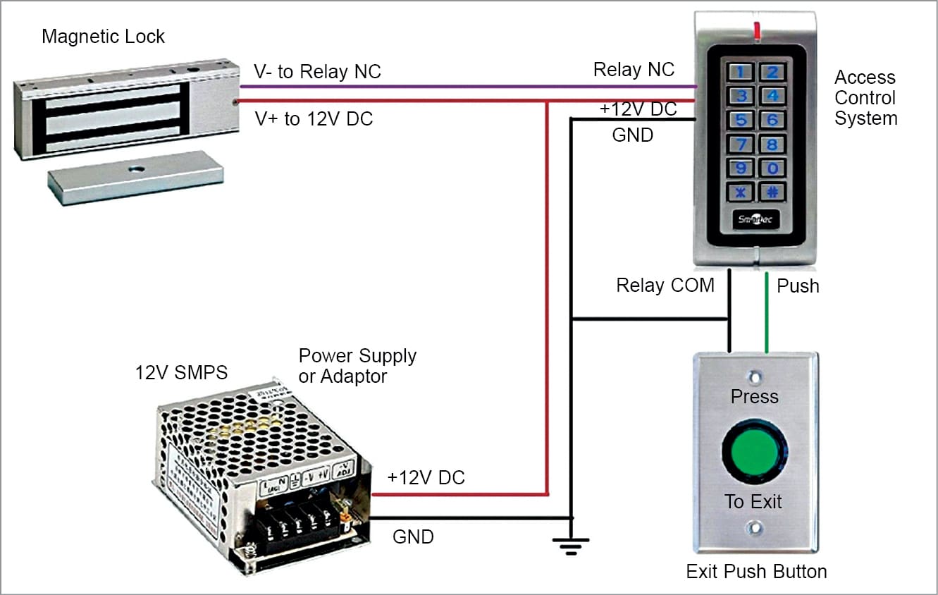
An RFID-based access control system functions by creating an electronically managed security barrier for a door, utilizing a combination of identification hardware, a central controller, and an electromechanical locking mechanism. At the heart of the system is the access control reader (SA32-E), which remains powered by a 12V, 3A DC power supply adaptor or SMPS. The reader continuously emits an electromagnetic field designed to detect compatible RFID tags when they are brought into close proximity. When a user presents a valid RFID tag, the reader captures the unique identifier encoded on the tag and compares it against its internal database or authorization logic. Upon successful verification, the reader changes the state of its internal relay or output signal, which governs the power delivered to the magnetic lock. The magnetic lock, specified here as a fail-safe type mounted securely with a dedicated bracket, relies on continuous electrical current to maintain a powerful magnetic field that tightly binds the armature plate to the electromagnet, keeping the door firmly shut. When the access control reader validates an authorized RFID tag, it temporarily cuts or interrupts power to the magnetic lock, releasing the magnetic hold and allowing the door to be opened. Conversely, if someone needs to exit from the secure side without an RFID tag, they press the exit push button, which is wired to the designated request-to-exit input terminals on the system. Pressing this button momentarily signals the control system to drop power to the magnetic lock, allowing safe egress. Throughout operation, robust connecting wires, such as Cat 6 or standard copper wires, ensure reliable power distribution and signal transmission between the 12V power supply, the SA32-E reader, the exit push button, and the magnetic lock.
Why Build This
Design and deploy an undergraduate-level security infrastructure suitable for controlling entry and exit in engineering laboratories, server rooms, and academic facilities.
Gain practical engineering experience interfacing electromechanical actuators, such as fail-safe magnetic locks, with digital access control readers and DC power supplies.
Understand the integration of hardwired safety egress paths, using exit push buttons to ensure compliance with building life-safety codes.
Real-World Application
Used in residential buildings, corporate offices, server rooms, and secure facilities to manage entry and exit permissions.
Skills You'll Learn
Access control system wiring
DC power distribution
relay output integration
fail-safe lock configuration
secure physical installation
Safety Precautions
Ensure power is disconnected before working on wiring connections, and verify correct DC voltage polarity to prevent damaging the access control device or magnetic lock.
Technology Tags
RFID
ACCESS CONTROL
RELAYS
MAGNETIC LOCK
SMART CARD
SECURITY SYSTEMS
Frequently Asked Questions
Because the system utilizes a fail-safe type magnetic lock, cutting power entirely causes the magnetic field to drop, automatically unlocking the door to ensure safe evacuation during an emergency.
You must use a compatible DC power supply adaptor or SMPS rated for 12V and at least 3A to safely and reliably power both the access control reader and the current-hungry magnetic lock without voltage drops.
An exit push button is wired directly to the system's request-to-exit inputs, which temporarily cuts power to the magnetic lock when pressed from the inside to allow immediate egress.
Gallery
This page is part of Kitkraft's Project Hub — a curated collection of electronics & robotics projects gathered from the maker community to help students and hobbyists discover and learn to build. Kitkraft does not claim authorship of the original project, and makes no representation as to the accuracy, completeness or safety of third-party source material. The summary and "How It Works" explanation above are AI-generated, rewritten with reference to the original tutorial — not a reproduction of it. Full credit and a direct link to the original source are provided above. If you're the original creator and have a concern about how your work is represented here, please contact us and we'll address it promptly.
Kitkraft Project Hub — curated from the maker community, credited at the source.
 MB102 Adjustable Breadboard Power Supply Module (3.3V & 5V) for Arduino & Raspberry Pi
Rs. 139.00
 2-Slot 18650 Holder with Protective Cover and On/Off Switch – Case
Rs. 109.00
 RFID Reader/Writer RC522 SPI S50 with RFID Card and Tag
Rs. 190.00
 400 Points Mini Solderless Prototype PCB Breadboard High Quality
Rs. 89.00
 Jumper Wire 10 Pin Male To Male 20cm
Rs. 45.00
 Jumper Wire 10 Pin Male To Female 20cm
Rs. 45.00


