This project is sourced from another site, not written by us — this list is our best match of their components against what we stock, not a verified bill of materials. Always check the original blog (linked above) for the actual parts list before buying.
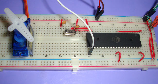
This project centers on controlling the angular position of a servo motor using an 8051 microcontroller, specifically the AT89S52 model. Servo motors operate by receiving Pulse Width Modulation (PWM) signals, where the duration of the high pulse dictates the precise shaft angle—typically ranging from 0 to 180 degrees. Because standard 8051 output pins provide digital high and low states without dedicated hardware PWM channels on basic models, engineers must write custom firmware using a C compiler like Keil uVision to generate precise delay loops and toggle an output pin manually. The microcontroller's GPIO pin connects to the servo motor's control input line, sending out these periodic control pulses. Meanwhile, the power supply or battery provides the necessary operating voltage and current to drive the servo motor, which typically demands more power than a standard microcontroller pin can safely source. Connecting wires complete the electrical paths between the AT89S52, the power source, and the motor. The programming device is used to flash the compiled C code onto the 8051 microcontroller. Once running, the microcontroller continuously executes the timer logic, allowing users to alter the output pulse width and dynamically command the servo to rotate to specific angles.
Why Build This
Master precise angular position control required for robotics and automated positioning systems.
Learn how to generate software-based Pulse Width Modulation (PWM) signals using an 8051 microcontroller.
Gain practical experience interfacing power-hungry actuators with low-power microcontrollers safely.
Real-World Application
Robotics, automated positioning systems, RC vehicles, and camera pan-tilt mechanisms.
Skills You'll Learn
PWM signal generation
actuator interfacing
microcontroller firmware development
embedded C programming
motor control principles
Safety Precautions
Ensure correct power supply voltage levels for the servo motor to prevent damage to the microcontroller or motor.
Technology Tags
8051
AT89S52
SERVO MOTOR
MICROCONTROLLER
PWM
EMBEDDED C
Frequently Asked Questions
No, servo motors draw significantly more current than an 8051 microcontroller pin or onboard regulator can safely supply. Always use a dedicated external power supply or battery for the servo, ensuring the grounds are common.
You can use Keil uVision or a similar 8051 C compiler to write, compile, and generate the hex file for your microcontroller.
A servo motor has an internal control circuit that interprets the width of incoming pulses to determine what exact angle the output shaft should turn to, rather than just spinning continuously with DC voltage.
Gallery
This page is part of Kitkraft's Project Hub — a curated collection of electronics & robotics projects gathered from the maker community to help students and hobbyists discover and learn to build. Kitkraft does not claim authorship of the original project, and makes no representation as to the accuracy, completeness or safety of third-party source material. The summary and "How It Works" explanation above are AI-generated, rewritten with reference to the original tutorial — not a reproduction of it. Full credit and a direct link to the original source are provided above. If you're the original creator and have a concern about how your work is represented here, please contact us and we'll address it promptly.
Kitkraft Project Hub — curated from the maker community, credited at the source.
 TowerPro SG90 Mini Servo – 180 degree Rotation – Standard Quality
Rs. 179.00
 Jumper Wire 10 Pin Male To Male 20cm
Rs. 45.00
 MB102 Adjustable Breadboard Power Supply Module (3.3V & 5V) for Arduino & Raspberry Pi
Rs. 139.00
 400 Points Mini Solderless Prototype PCB Breadboard High Quality
Rs. 89.00
 Jumper Wire 10 Pin Male To Female 20cm
Rs. 45.00


