This project is sourced from another site, not written by us — this list is our best match of their components against what we stock, not a verified bill of materials. Always check the original blog (linked above) for the actual parts list before buying.
This list includes a generic resistor set
as a placeholder — it is not matched to the exact value or part number this circuit needs. The correct one is specified on the original source page linked above; check it before buying.
We don't carry yet: Microcontroller IC (DIP) / Chip
Capacitors
9V Battery + Snap
Header Pins / Terminals / Connectors
Speaker / Audio Amplifier
Custom PCB / PCB Fab
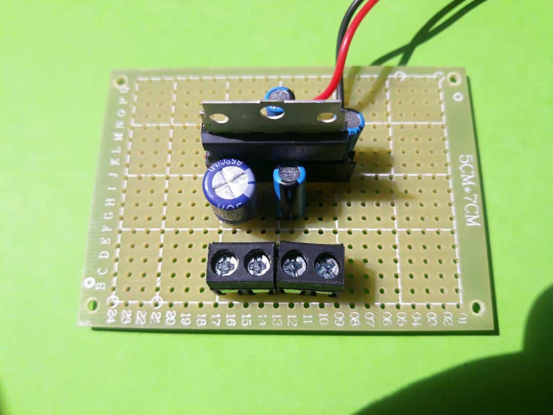
This audio frequency amplifier circuit is built around the AN7523 integrated circuit, which functions as the core active amplifying element designed to boost weak audio input signals to a level capable of driving a loudspeaker. Power is supplied by a 9V battery, which provides the necessary DC voltage rail to energize the internal transistor stages of the AN7523 IC. Input audio signals are coupled into the circuit via capacitors such as C2 and C4, which block DC voltage components while allowing AC audio signals to pass through. The resistor network consisting of R1 (47K), R2 (33K), and the 10K preset potentiometer (VR1) acts as a voltage divider and biasing configuration, allowing the user to adjust the input signal level or volume going into the amplifier stage. Electrolytic capacitors like C1 (470µF/25V) and C3 (10µF/25V) serve vital filtering and decoupling roles, stabilizing the power supply rails by shunting high-frequency noise to ground and providing charge storage to support sudden bass transients demanded by the 8Ω/3W speaker. The amplified output signal is then delivered directly to the speaker through the 2-pin socket and connector wires, converting the electrical audio waveforms back into audible sound waves. The entire circuit is assembled on a custom PCB using an 18-pin IC socket to safely mount the AN7523 without exposing it to excessive soldering heat.
Why Build This
Gain hands-on experience designing and troubleshooting linear analog power amplification stages suitable for undergraduate engineering laboratories.
Understand the practical implementation of integrated audio power amplifiers, coupling capacitors, and biasing resistor networks in miniature electronic systems.
Build a functional, portable 2.5W audio output device suitable for small-scale portable sound amplification projects.
Real-World Application
Miniature audio systems, portable speakers, and small DIY sound amplification gadgets.
Skills You'll Learn
analog audio amplification
power supply decoupling
resistor biasing networks
volume control implementation
PCB assembly
electrolytic capacitor polarity management
Safety Precautions
Ensure correct polarity when connecting the 9V battery and electrolytic capacitors to prevent component damage.
Technology Tags
AUDIO AMPLIFICATION
ANALOG ELECTRONICS
AN7523 IC
PCB DESIGN
AUDIO FREQUENCY
SPEAKER
Frequently Asked Questions
VR1 acts as an adjustable potentiometer (or preset) used to control the amplitude of the input audio signal, effectively serving as a volume adjustment control for the amplifier.
C1 through C4 are electrolytic capacitors containing liquid electrolyte, meaning connecting them backward or reversing the 9V battery terminals will cause internal dielectric breakdown, leading to component failure, leakage, or potential rupture.
While the circuit is optimized for an 8Ω/3W speaker, using a lower impedance speaker could draw excessive current and overheat the AN7523 IC, while a significantly higher impedance speaker will reduce the maximum output volume.
Gallery
This page is part of Kitkraft's Project Hub — a curated collection of electronics & robotics projects gathered from the maker community to help students and hobbyists discover and learn to build. Kitkraft does not claim authorship of the original project, and makes no representation as to the accuracy, completeness or safety of third-party source material. The summary and "How It Works" explanation above are AI-generated, rewritten with reference to the original tutorial — not a reproduction of it. Full credit and a direct link to the original source are provided above. If you're the original creator and have a concern about how your work is represented here, please contact us and we'll address it promptly.
Kitkraft Project Hub — curated from the maker community, credited at the source.
 10pcs - 220 ohm 1/4 W Resistor Set
Rs. 39.00
 Jumper Wire 10 Pin Male To Male 20cm
Rs. 45.00
 400 Points Mini Solderless Prototype PCB Breadboard High Quality
Rs. 89.00
 MB102 Adjustable Breadboard Power Supply Module (3.3V & 5V) for Arduino & Raspberry Pi
Rs. 139.00
 Jumper Wire 10 Pin Male To Female 20cm
Rs. 45.00


