This project is sourced from another site, not written by us — this list is our best match of their components against what we stock, not a verified bill of materials. Always check the original blog (linked above) for the actual parts list before buying.
This list includes a generic resistor set
as a placeholder — it is not matched to the exact value or part number this circuit needs. The correct one is specified on the original source page linked above; check it before buying.
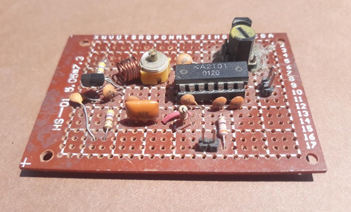
This intermediate-level project implements an analog FM radio receiver designed to capture standard 88-108 MHz broadcast signals. The signal capture begins at the front end with the BF494 RF transistor, which handles initial radio frequency amplification and helps tune into the desired frequency band alongside the various passive capacitors (such as the 47pF, 68pF, 33pF, and 0.04uF values) and tuning elements. The core demodulation and intermediate processing rely on the 14-pin KA2101 integrated circuit, seated securely in an IC socket on the 5cm x 7.5cm Vero board. The KA2101 works in conjunction with components like the 5.5 MHz IFT coils or 5.5 MHz ceramic filters to isolate the intermediate frequency and extract the audio signal from the carrier wave. Because the KA2101 handles signal processing rather than heavy audio driving, the extracted audio output is routed to an external audio amplifier section—built around a TBA 810 or TBA 820 IC and speaker—to drive audible sound waves into the room. The entire analog system is powered by a standard 9V battery and clip, making it a completely self-contained analog receiver circuit built without any programmable microcontrollers or software.
Why Build This
Explore undergraduate-level analog receiver design by implementing classic superheterodyne principles with discrete RF components and specialized ICs.
Gain practical hands-on experience assembling radio frequency circuits on Vero board, managing component placement and parasitic capacitances critical to 88-108 MHz tuning.
Bridge RF signal processing with audio output stages by successfully interfacing the KA2101 receiver circuit with an external TBA 810 or TBA 820 audio amplifier.
Real-World Application
Basic FM radio broadcasting reception, educational demonstration of superheterodyne receiver principles, and audio electronics experimentation.
Skills You'll Learn
RF transistor biasing
analog signal demodulation
superheterodyne receiver tuning
intermediate frequency (IF) filtering
Vero board circuit layout
audio amplifier interfacing
Safety Precautions
Ensure correct polarity when connecting the 9V battery and use a low-wattage (25W) soldering iron carefully.
Technology Tags
FM RADIO
KA2101 IC
BF494 TRANSISTOR
RF AMPLIFIER
OSCILLATOR
MIXER
IF AMPLIFIER
ANALOG ELECTRONICS
AUDIO PREAMPLIFIER
Frequently Asked Questions
No, this is a purely analog circuit built on a Vero board. It relies entirely on hardware components like the KA2101 IC and BF494 transistor to receive and demodulate FM signals without any software or programming.
The KA2101 IC processes the radio signals and extracts the audio, but it does not have a high-power output stage capable of directly driving a speaker. The external amplifier is needed to boost the audio signal to an audible volume.
Yes, but the project data specifies using a low-wattage 25W soldering iron carefully to avoid damaging sensitive semiconductor pins and ICs during Vero board assembly.
Gallery
This page is part of Kitkraft's Project Hub — a curated collection of electronics & robotics projects gathered from the maker community to help students and hobbyists discover and learn to build. Kitkraft does not claim authorship of the original project, and makes no representation as to the accuracy, completeness or safety of third-party source material. The summary and "How It Works" explanation above are AI-generated, rewritten with reference to the original tutorial — not a reproduction of it. Full credit and a direct link to the original source are provided above. If you're the original creator and have a concern about how your work is represented here, please contact us and we'll address it promptly.
Kitkraft Project Hub — curated from the maker community, credited at the source.
 10pcs - 220 ohm 1/4 W Resistor Set
Rs. 39.00
 400 Points Mini Solderless Prototype PCB Breadboard High Quality
Rs. 89.00
 MB102 Adjustable Breadboard Power Supply Module (3.3V & 5V) for Arduino & Raspberry Pi
Rs. 139.00
 Jumper Wire 10 Pin Male To Male 20cm
Rs. 45.00
 Jumper Wire 10 Pin Male To Female 20cm
Rs. 45.00


