Project Hub
/Basic Analog & Power Electronics/Power Supplies & Voltage Regulators/Simple FM Radio Using LA1260
Beginner
ANALOG / DISCRETE
< ₹500
3 – 6 Hours
Partial Kit
Simple FM Radio Using LA1260
A simple and low-cost FM radio circuit built using the LA1260 IC and a BF494 transistor, designed to operate on a 5.5 MHz IF frequency for easy component availability.
This project is sourced from another site, not written by us — this list is our best match of their components against what we stock, not a verified bill of materials. Always check the original blog (linked above) for the actual parts list before buying.
This list includes a generic resistor set
as a placeholder — it is not matched to the exact value or part number this circuit needs. The correct one is specified on the original source page linked above; check it before buying.
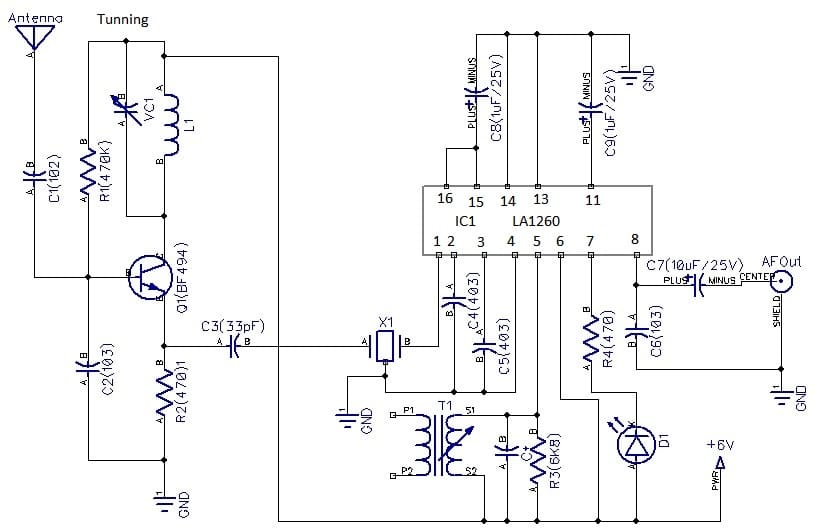
This project implements a classic superheterodyne FM radio receiver built around the LA1260 dedicated radio receiver IC and a BF494 RF transistor. Operating on a compact 5cm x 7cm Veroboard, the circuit uses a 75cm wire antenna to capture frequency-modulated radio signals from the air. The incoming RF signal is fed into the front-end stage featuring the BF494 transistor, which handles initial amplification and mixes the signal. The LA1260 IC then takes over the core superheterodyne processing, which includes intermediate frequency (IF) amplification and demodulation. A 5.5MHz IFT coil and a matching 5.5MHz 3-pin ceramic filter are employed to establish the specific intermediate frequency stage, ensuring precise channel selectivity and filtering out unwanted frequencies. Tuning is managed by a variable 2-22pF trimmer capacitor alongside fixed capacitors and resistors (such as the 470K, 6K8, and 470 ohm variants) that set the necessary biasing and time constants for stable operation. Decoupling and coupling are handled by various capacitors, including 10uF/25V and 1uF/25V electrolytics as well as smaller ceramic disks like 102 and 103 codes. Once the LA1260 successfully demodulates the audio information from the 5.5MHz IF carrier, the resulting audio frequency (AF) signal is outputted to an external AF amplifier and speaker system so the broadcast can be heard clearly. The entire analog system runs reliably on a modest +6V DC power supply.
Why Build This
Gain hands-on undergraduate-level experience with superheterodyne receiver topology and RF demodulation.
Understand the practical integration of dedicated radio ICs like the LA1260 with discrete analog components like the BF494 transistor.
Learn how to manually tune and filter radio frequencies using physical IFT coils, ceramic filters, and trimmer capacitors.
Real-World Application
Educational demonstration of radio frequency (RF) reception, superheterodyne principles, and building analog consumer entertainment electronics from recycled or readily available components.
Skills You'll Learn
RF circuit construction
superheterodyne receiver tuning
intermediate frequency filtering
analog signal demodulation
transistor biasing
Veroboard prototyping
Safety Precautions
Ensure proper handling of soldering equipment and maintain correct polarity when connecting the +6V DC power supply and electrolytic capacitors.
Technology Tags
FM RADIO
LA1260 IC
BF494 TRANSISTOR
ANALOG ELECTRONICS
RF CIRCUIT
VEROBOARD
IFT COIL
CERAMIC FILTER
Frequently Asked Questions
The LA1260 IC outputs a low-level audio frequency (AF) signal that contains the broadcast sound, but it lacks a built-in power amplifier strong enough to drive a standalone speaker directly.
They work together to set and filter the intermediate frequency (IF) stage of the superheterodyne receiver, helping to select the desired station cleanly while rejecting adjacent interference.
You should strictly use a +6V power supply as specified in the project parameters to prevent exceeding the operating voltage limits of the LA1260 IC and associated analog components.
Gallery
This page is part of Kitkraft's Project Hub — a curated collection of electronics & robotics projects gathered from the maker community to help students and hobbyists discover and learn to build. Kitkraft does not claim authorship of the original project, and makes no representation as to the accuracy, completeness or safety of third-party source material. The summary and "How It Works" explanation above are AI-generated, rewritten with reference to the original tutorial — not a reproduction of it. Full credit and a direct link to the original source are provided above. If you're the original creator and have a concern about how your work is represented here, please contact us and we'll address it promptly.
Kitkraft Project Hub — curated from the maker community, credited at the source.
 10pcs - 220 ohm 1/4 W Resistor Set
Rs. 39.00
 MB102 Adjustable Breadboard Power Supply Module (3.3V & 5V) for Arduino & Raspberry Pi
Rs. 139.00
 400 Points Mini Solderless Prototype PCB Breadboard High Quality
Rs. 89.00
 Jumper Wire 10 Pin Male To Male 20cm
Rs. 45.00
 Jumper Wire 10 Pin Male To Female 20cm
Rs. 45.00


