An electronic water tank overflow stopper that uses a magnetic float sensor attached to the overflow pipe to control a pump motor via a 555 timer bistable multivibrator circuit.
This project is sourced from another site, not written by us — this list is our best match of their components against what we stock, not a verified bill of materials. Always check the original blog (linked above) for the actual parts list before buying.
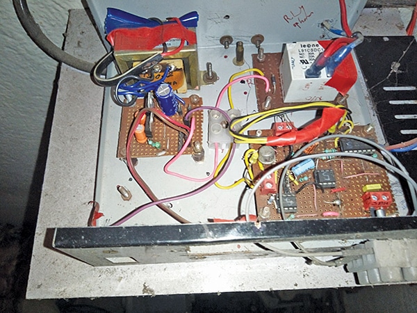
The Simple Overflow Stopper circuit is designed to automatically manage water levels and prevent tank overflow using a combination of discrete components and an analog control scheme. At the heart of the system is a magnetic float sensor, specifically the FS37A, which is installed on the tank's overflow pipe to act as a mechanical switch changing states based on water level. This sensor interfaces with a 555 timer IC configured in a bistable multivibrator mode, allowing the circuit to latch its output state upon receiving a trigger from the float sensor. Powering the control electronics is a step-down transformer (230V to 12V-0-12V, 600mA) working in conjunction with 1N4007 diodes to form a rectification stage, and electrolytic capacitors like C1 to smooth the DC supply voltage. When the water reaches the critical level, the magnetic float sensor changes position, sending a signal that causes the 555 timer output to switch states. This output drives a transistor (T1), which acts as a solid-state switch providing sufficient current to actuate an electromagnetic relay. The relay, in turn, physically opens or closes the circuit connected to the pump motor, stopping its operation before an overflow can occur. Built on a general-purpose PCB using connecting wires, this analog setup operates entirely in hardware without the need for microcontrollers or software programming.
Why Build This
Design a reliable, microcontroller-free automation system suitable for residential and commercial water tank management to prevent water wastage.
Gain practical undergraduate-level experience integrating electromechanical relays and discrete sensors with linear power supplies.
Implement automated intrusion and event detection logic using classic analog timing and latching integrated circuits.
Real-World Application
Residential and commercial water tank management to prevent water wastage, overflow, and unnecessary pump operation.
Skills You'll Learn
Step-down transformer power supply design
AC-to-DC rectification with diodes
555 timer bistable multivibrator configuration
transistor switching circuits
electromechanical relay interfacing
Safety Precautions
Exercise caution when dealing with mains AC voltage (230V) for the step-down transformer and pump relay connections.
Technology Tags
555 TIMER
MAGNETIC FLOAT SENSOR
RELAY CONTROL
WATER LEVEL DETECTOR
POWER SUPPLY
PCB DESIGN
Frequently Asked Questions
No, this project is entirely analog. It uses a 555 timer IC configured in bistable mode and discrete hardware components, so no software or programming is required.
The magnetic float sensor (FS37A) acts as a physical switch that changes its contact state when the water reaches a certain level, sending a trigger or reset signal to the 555 timer to change the output state of the bistable circuit.
The transformer steps down the high mains voltage (230V AC) to a safer lower voltage (12V-0-12V AC), which is then rectified and filtered to supply safe DC power to the 555 timer and relay circuitry.
Gallery
This page is part of Kitkraft's Project Hub — a curated collection of electronics & robotics projects gathered from the maker community to help students and hobbyists discover and learn to build. Kitkraft does not claim authorship of the original project, and makes no representation as to the accuracy, completeness or safety of third-party source material. The summary and "How It Works" explanation above are AI-generated, rewritten with reference to the original tutorial — not a reproduction of it. Full credit and a direct link to the original source are provided above. If you're the original creator and have a concern about how your work is represented here, please contact us and we'll address it promptly.
Kitkraft Project Hub — curated from the maker community, credited at the source.
 LM2596 Step Down DC-DC Buck Converter
Rs. 99.00
 5V 1 Channel Relay Module
Rs. 45.00
 Jumper Wire 10 Pin Male To Male 20cm
Rs. 45.00
 400 Points Mini Solderless Prototype PCB Breadboard High Quality
Rs. 89.00
 MB102 Adjustable Breadboard Power Supply Module (3.3V & 5V) for Arduino & Raspberry Pi
Rs. 139.00
 Jumper Wire 10 Pin Male To Female 20cm
Rs. 45.00


