This project is sourced from another site, not written by us — this list is our best match of their components against what we stock, not a verified bill of materials. Always check the original blog (linked above) for the actual parts list before buying.
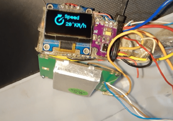
The Smart Radar System leverages the Doppler effect to measure the velocity of moving objects in real-time. At the heart of the system is the HB100 microwave radar module, which transmits a continuous microwave signal and receives the reflection bouncing off a moving target. Because of the relative motion between the radar and the object, the frequency of the reflected wave shifts slightly. This frequency shift, known as the Doppler shift, is proportional to the speed of the moving object. However, the raw output signal generated by the HB100's internal mixer is very weak and often contains high-frequency noise. To make this signal usable by the microcontroller, it is routed through an external preamplifier circuit, which boosts the weak Doppler signal and conditions the waveform. The conditioned analog signal is then read by the Arduino board. Using the Analog Frequency library, the Arduino processes the incoming signal to calculate the velocity value. Finally, the computed speed data is rendered visually onto an OLED display module, which interfaces with the microcontroller to provide a clear, real-time readout for the user.
Why Build This
Design and deploy an undergraduate-level embedded sensing instrument capable of real-time velocity measurement using microwave Doppler principles.
Gain practical experience processing low-level analog sensor signals by combining hardware preamplification with microcontroller-based frequency analysis.
Interface specialized RF sensing hardware with display peripherals to build functional instrumentation systems for traffic and industrial monitoring applications.
No specific precautions noted for this build — always follow general electronics safety practices.
Technology Tags
RADAR
DOPPLER EFFECT
MICROWAVE SENSOR
HB100
OLED DISPLAY
ARDUINO
SIGNAL PROCESSING
C++
VELOCITY MEASUREMENT
Frequently Asked Questions
The raw output signal from the HB100 microwave sensor is typically in the millivolt range and prone to noise. The preamplifier boosts and conditions this weak signal so that the Arduino's analog inputs can reliably detect and measure the frequency shift.
The standard HB100 module features a single-channel output, which allows for measuring the magnitude of the velocity (speed) based on the Doppler frequency, but it cannot inherently determine whether the object is moving toward or away from the sensor.
You will need the Analog Frequency library to process the incoming Doppler signals into readable velocity values and the U8g2 library to drive the OLED display module.
Gallery
This page is part of Kitkraft's Project Hub — a curated collection of electronics & robotics projects gathered from the maker community to help students and hobbyists discover and learn to build. Kitkraft does not claim authorship of the original project, and makes no representation as to the accuracy, completeness or safety of third-party source material. The summary and "How It Works" explanation above are AI-generated, rewritten with reference to the original tutorial — not a reproduction of it. Full credit and a direct link to the original source are provided above. If you're the original creator and have a concern about how your work is represented here, please contact us and we'll address it promptly.
 RCWL-0516 Microwave Radar Sensor
Rs. 59.00
 0.96 Inch I2C/IIC 4pin OLED Display Module White
Rs. 349.00
 Jumper Wire 10 Pin Male To Male 20cm
Rs. 45.00
 MB102 Adjustable Breadboard Power Supply Module (3.3V & 5V) for Arduino & Raspberry Pi
Rs. 139.00
 400 Points Mini Solderless Prototype PCB Breadboard High Quality
Rs. 89.00
 Jumper Wire 10 Pin Male To Female 20cm
Rs. 45.00


