This project is sourced from another site, not written by us — this list is our best match of their components against what we stock, not a verified bill of materials. Always check the original blog (linked above) for the actual parts list before buying.
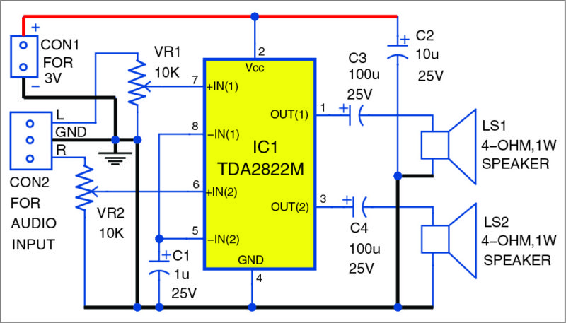
The TDA2822 Amplifier Circuit is a classic dual-channel audio amplifier built around the TDA2822M IC, which is securely housed in an 8-pin DIP socket on a printed circuit board (PCB). The system is powered by a low-voltage 3V DC source, typically provided by two 1.5V AA batteries or a lithium-ion cell, connected via wires. Incoming audio signals—such as those from a mobile device—are fed into the circuit through dual potentiometers (VR1 and VR2), which act as volume controls by adjusting the amplitude of the signal before it reaches the amplifier inputs. The TDA2822M IC takes these low-level audio signals and increases their power to drive two small speakers (LS1 and LS2) for stereo sound output. To ensure stable operation, a network of four electrolytic capacitors (C1 through C4) is integrated into the circuit. These capacitors serve critical roles in power supply decoupling, filtering out voltage ripples, and blocking DC bias while coupling the AC audio signals to the speakers. As current flows from the power source through the IC and the passive components, the integrated circuit modulates the electrical energy in sync with the audio waveform, translating the amplified electrical signals into audible sound waves through the speakers.
Why Build This
Design and analyze a functional two-channel analog audio power amplifier stage suitable for portable consumer electronics.
Investigate the practical application of linear integrated circuits, power supply decoupling, and impedance matching in audio engineering.
Gain hands-on experience with PCB assembly, component placement, and signal routing for low-voltage analog circuitry.
Real-World Application
Portable mobile speakers, mini audio systems, personal listening devices, and small DIY sound amplification setups.
Skills You'll Learn
analog audio circuit assembly
dual-channel volume control implementation
power supply decoupling
electrolytic capacitor polarity management
PCB wiring and soldering
Safety Precautions
Ensure correct polarity when connecting the 3V to 6V DC power supply and electrolytic capacitors to prevent component damage or leakage.
Technology Tags
AUDIO AMPLIFIER
TDA2822M IC
PCB DESIGN
ANALOG ELECTRONICS
VOLUME CONTROL
SPEAKERS
Frequently Asked Questions
Connecting the power supply in reverse polarity can instantly damage the TDA2822M IC and cause the electrolytic capacitors to fail, potentially leading to leakage or overheating. Always double-check your positive and negative connections before powering the circuit.
The TDA2822M typically supports voltages up to 6V DC, but staying close to the recommended 3V to 6V range is crucial. Exceeding this limit can cause thermal overload and permanent damage to the integrated circuit.
Electrolytic capacitors are polarized components. Installing them with the wrong orientation can cause them to fail short-circuit, leak, or rupture when voltage is applied. Always match the stripe on the capacitor body to the negative terminal marking on the PCB.
Gallery
This page is part of Kitkraft's Project Hub — a curated collection of electronics & robotics projects gathered from the maker community to help students and hobbyists discover and learn to build. Kitkraft does not claim authorship of the original project, and makes no representation as to the accuracy, completeness or safety of third-party source material. The summary and "How It Works" explanation above are AI-generated, rewritten with reference to the original tutorial — not a reproduction of it. Full credit and a direct link to the original source are provided above. If you're the original creator and have a concern about how your work is represented here, please contact us and we'll address it promptly.
Kitkraft Project Hub — curated from the maker community, credited at the source.
 MB102 Adjustable Breadboard Power Supply Module (3.3V & 5V) for Arduino & Raspberry Pi
Rs. 139.00
 Jumper Wire 10 Pin Male To Male 20cm
Rs. 45.00
 400 Points Mini Solderless Prototype PCB Breadboard High Quality
Rs. 89.00
 Jumper Wire 10 Pin Male To Female 20cm
Rs. 45.00


