This project is sourced from another site, not written by us — this list is our best match of their components against what we stock, not a verified bill of materials. Always check the original blog (linked above) for the actual parts list before buying.
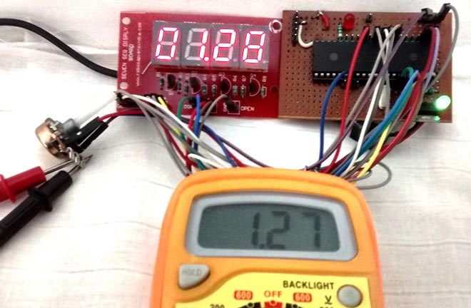
This project centers on interfacing an analog sensor simulation with a PIC16F877A microcontroller by utilizing its built-in Analog-to-Digital Converter (ADC) module. The circuit is assembled on a breadboard, where a potentiometer is connected to a designated analog input pin of the microcontroller to act as a variable voltage divider. By adjusting the potentiometer's wiper, you manually alter the analog voltage supplied to the PIC pin, sweeping continuously between ground and the reference supply voltage.
To process this physical phenomenon inside a digital processor, the microcontroller's internal ADC module samples the continuous analog voltage and translates it into a discrete digital value based on its bit-resolution. Writing the software requires using MPLAB IDE along with the XC8 compiler to configure the special function registers that control the ADC channels, clock selection, and result formatting. Once the C code initializes the hardware and initiates a conversion cycle, the register captures the digital equivalent of the analog voltage. This setup effectively demonstrates how modern embedded systems bridge the gap between physical, real-world analog signals and computational digital logic, allowing engineers to read and evaluate sensor inputs programmatically.
Why Build This
Develop foundational competence in reading variable sensor inputs for undergraduate engineering design projects.
Gain practical experience programming microcontroller hardware peripherals using industry-standard tools like MPLAB and XC8.
Understand the underlying principles of signal conversion required for building custom digital multimeters and voltmeters.
Real-World Application
Used in sensor reading, temperature monitoring systems, voltage measurement devices, and any embedded system requiring the processing of analog signals.
Skills You'll Learn
Analog-to-digital conversion
Microcontroller register configuration
Embedded C programming
Sensor signal conditioning
Analog input interfacing
Safety Precautions
No specific precautions noted for this build — always follow general electronics safety practices.
Technology Tags
PIC MICROCONTROLLER
PIC16F877A
ADC
ANALOG-TO-DIGITAL CONVERTER
MPLAB
XC8
C PROGRAMMING
EMBEDDED SYSTEMS
Frequently Asked Questions
The potentiometer acts as a safe, adjustable voltage source that lets you manually vary the analog input to the microcontroller's ADC pin to test different conversion values.
You need the MPLAB IDE to write and manage your project, the XC8 compiler to build the C source code into a binary, and a compatible programmer/debugger to flash it onto the PIC microcontroller.
Yes, any sensor that outputs a variable analog voltage—such as a temperature sensor or pressure transducer—can replace the potentiometer as long as its output voltage stays within the PIC's allowable input range.
Gallery
This page is part of Kitkraft's Project Hub — a curated collection of electronics & robotics projects gathered from the maker community to help students and hobbyists discover and learn to build. Kitkraft does not claim authorship of the original project, and makes no representation as to the accuracy, completeness or safety of third-party source material. The summary and "How It Works" explanation above are AI-generated, rewritten with reference to the original tutorial — not a reproduction of it. Full credit and a direct link to the original source are provided above. If you're the original creator and have a concern about how your work is represented here, please contact us and we'll address it promptly.
Kitkraft Project Hub — curated from the maker community, credited at the source.
 MB102 Adjustable Breadboard Power Supply Module (3.3V & 5V) for Arduino & Raspberry Pi
Rs. 139.00
 Jumper Wire 10 Pin Male To Male 20cm
Rs. 45.00
 400 Points Mini Solderless Prototype PCB Breadboard High Quality
Rs. 89.00
 Jumper Wire 10 Pin Male To Female 20cm
Rs. 45.00


