This project is sourced from another site, not written by us — this list is our best match of their components against what we stock, not a verified bill of materials. Always check the original blog (linked above) for the actual parts list before buying.
This list includes a generic resistor set
as a placeholder — it is not matched to the exact value or part number this circuit needs. The correct one is specified on the original source page linked above; check it before buying.
We don't carry yet: Microcontroller IC (DIP) / Chip
Diodes (1N4007 / 1N4148 / Schottky / Zener)
Thyristor / SCR / Triac / Varistor / Fuse
Inductors / Coils / Ferrite
Transformer
Voltage Regulator IC (7805 / LM317 / 1117)
Optocoupler (PC817 / 4N35)
Capacitors
Custom PCB / PCB Fab
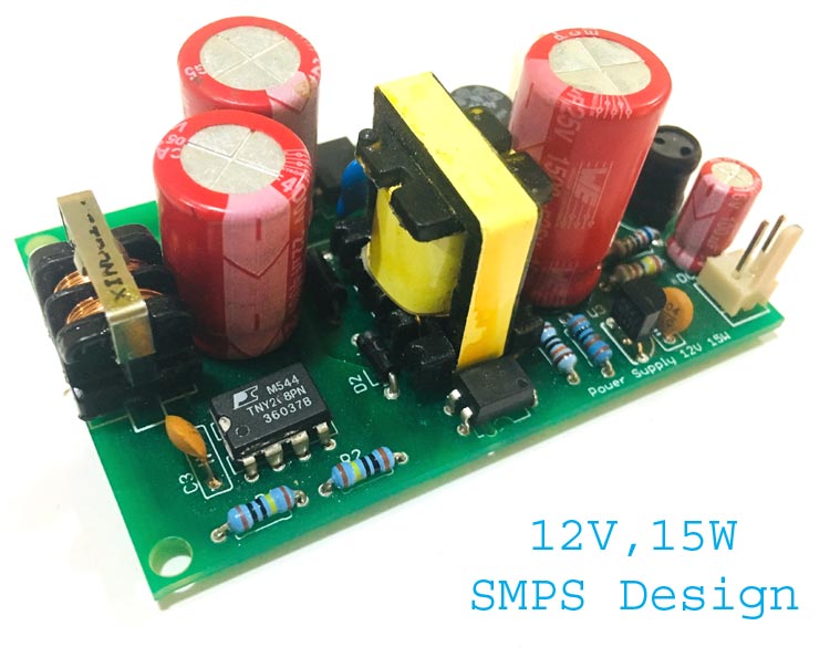
This project designs a custom PCB-based Switched-Mode Power Supply (SMPS) capable of delivering a regulated 12V output from a high-voltage AC mains input ranging from 85V to 265V AC. The power conversion process begins at the input stage, where incoming AC power passes through a 1A 250VAC slow blow fuse (F1) for overcurrent protection, a 7mm 275V metal oxide varistor (RV1) to absorb voltage surges, and a common mode choke (L1) to suppress electromagnetic interference. The filtered AC voltage is then rectified into DC using a DB107 full bridge rectifier and smoothed out by high-voltage input capacitors (C1, C2). The core of the power conversion is managed by the TNY268PN power management IC, which works in conjunction with a switching transformer to efficiently step down the high DC voltage through high-frequency switching. On the secondary output side, diodes (such as D1, D2, D6) and output capacitors (C3 through C7) rectify and filter the transformer's high-frequency output into a steady DC voltage. To ensure tight regulation, a TL431 shunt regulator and an optocoupler form a feedback loop across the isolation barrier, communicating output voltage fluctuations back to the primary-side TNY268PN IC to dynamically adjust the switching duty cycle. The overall circuit layout and transformer characteristics are calculated and optimized using PI Expert software before being fabricated onto a custom PCB.
Why Build This
Design a reliable, isolated 12V DC power supply from standard AC mains for undergraduate engineering lab benchmarks or custom hardware prototypes.
Learn industry-standard power electronics layout techniques by routing a custom PCB for high-voltage AC-to-DC conversion.
Implement closed-loop voltage regulation using an optocoupler and a TL431 shunt regulator to maintain stable output under varying loads.
Real-World Application
Used as an internal power supply for small electronics, adapters, or as a charger for lead-acid and lithium batteries.
Skills You'll Learn
AC-DC power conversion design
high-voltage PCB layout and creepage/clearance management
transformer-based switching power supplies
closed-loop feedback regulation with optocouplers and shunt regulators
electromagnetic interference (EMI) filtering
Safety Precautions
Exercise extreme caution when working with high-voltage AC mains (85-265V AC). Ensure proper discharge of high-voltage capacitors and follow safe soldering and testing procedures.
Technology Tags
SMPS
POWER SUPPLY
AC-DC CONVERSION
PCB DESIGN
TNY268PN
FLYBACK CONVERTER
TRANSFORMER
OPTOCOUPLER
SURGE PROTECTION
Frequently Asked Questions
PI Expert software is used to calculate the electrical parameters and winding specifications for the switching transformer and other critical components based on your specific input and output requirements.
No, because this circuit deals with dangerous high-voltage AC mains (85-265V AC) and high-frequency switching, it must be built on the designated custom PCB rather than an open breadboard.
They provide galvanic isolation while creating a feedback path that monitors the output voltage and signals the primary-side TNY268PN IC to adjust switching behavior for a stable 12V output.
Gallery
This page is part of Kitkraft's Project Hub — a curated collection of electronics & robotics projects gathered from the maker community to help students and hobbyists discover and learn to build. Kitkraft does not claim authorship of the original project, and makes no representation as to the accuracy, completeness or safety of third-party source material. The summary and "How It Works" explanation above are AI-generated, rewritten with reference to the original tutorial — not a reproduction of it. Full credit and a direct link to the original source are provided above. If you're the original creator and have a concern about how your work is represented here, please contact us and we'll address it promptly.
 10pcs - 220 ohm 1/4 W Resistor Set
Rs. 39.00
 400 Points Mini Solderless Prototype PCB Breadboard High Quality
Rs. 89.00
 MB102 Adjustable Breadboard Power Supply Module (3.3V & 5V) for Arduino & Raspberry Pi
Rs. 139.00
 Jumper Wire 10 Pin Male To Male 20cm
Rs. 45.00
 Jumper Wire 10 Pin Male To Female 20cm
Rs. 45.00


