This project is sourced from another site, not written by us — this list is our best match of their components against what we stock, not a verified bill of materials. Always check the original blog (linked above) for the actual parts list before buying.
This list includes a generic resistor set
as a placeholder — it is not matched to the exact value or part number this circuit needs. The correct one is specified on the original source page linked above; check it before buying.
We don't carry yet: Diodes (1N4007 / 1N4148 / Schottky / Zener)
Capacitors
Microcontroller IC (DIP) / Chip
Optocoupler (PC817 / 4N35)
Inductors / Coils / Ferrite
LM35 / Analog Temp Sensor
Transformer
Custom PCB / PCB Fab
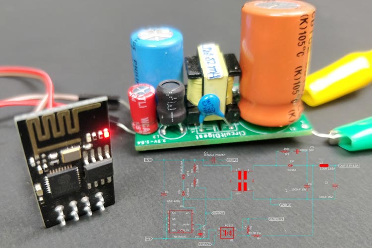
This compact Switched-Mode Power Supply converts high-voltage AC mains into a stable, regulated 3.3V DC output capable of delivering up to 1.5A. Mains AC first passes through an NTC inrush current limiter and an ABS8 surface-mount diode bridge rectifier, converting the alternating current into a high-voltage pulsating DC. A 22uF/400V bulk storage capacitor smooths this rectified voltage, while a 0.068nF 250VAC capacitor and a 2.2nF 250VAC capacitor handle electromagnetic interference (EMI) filtering. The TNY284DG switching IC integrates a power MOSFET and controller to chop the high-voltage DC at high frequencies, driving the custom EE13 transformer core to step the voltage down safely. On the secondary side, an SS34A Schottky diode rectifies the low-voltage high-frequency output, which is then filtered by a robust 3300uF 16V capacitor and a 3.3uH drum core inductor to produce a clean 3.3V rail. Feedback for tight voltage regulation is achieved using a TL431 precision shunt regulator and a PC817 optocoupler, which optically isolate the secondary output from the primary side while feeding error-correction signals back to the TNY284DG IC. Additional protective and supporting components—such as the SMBJ160A Zener diode, various surface-mount resistors, and small ceramic capacitors—configure switching dynamics, clamping voltage spikes and ensuring stable, reliable operation within tight physical dimensions.
Why Build This
Design a custom, highly efficient offline power supply capable of fitting into extremely space-constrained IoT and embedded enclosures.
Gain practical undergraduate-level experience with isolated flyback converter topologies, primary-side switching ICs, and optocoupler-based feedback networks.
Integrate mains-connected components, EMI filtering, and secondary-side synchronous or Schottky rectification onto a custom-designed printed circuit board.
Real-World Application
Providing regulated low-voltage DC power from mains AC in space-constrained IoT devices, smart home sensors, and embedded microcontroller systems.
Skills You'll Learn
Switched-mode power supply design
isolated feedback loop configuration
high-voltage PCB layout techniques
electromagnetic interference (EMI) filtering
schematic capture and board routing using CadSoft EAGLE
Safety Precautions
This circuit handles high mains AC voltage (185VAC-230VAC) and lacks integrated surge and fuse protection. Exercise extreme caution, use an isolation transformer or auto-transformer during testing, and add appropriate external input protections if deploying outside of a controlled hobbyist environment.
Technology Tags
SMPS
POWER SUPPLY
FLYBACK CONVERTER
PCB DESIGN
TNY284DG
AC-DC CONVERSION
TRANSFORMER DESIGN
Frequently Asked Questions
The optocoupler provides galvanic isolation between the dangerous high-voltage AC primary side and the low-voltage DC secondary side, allowing the output voltage status to safely signal the primary-side switching IC.
No, because this circuit connects directly to mains AC voltage (185VAC-230VAC) and lacks integrated fuse protection, you must use an isolation transformer or auto-transformer during testing to prevent severe electric shock.
The TNY284DG houses an internal power MOSFET and controller that rapidly switches the primary winding of the EE13 transformer, regulating the energy transferred to the secondary side to maintain a steady 3.3V output.
Gallery
This page is part of Kitkraft's Project Hub — a curated collection of electronics & robotics projects gathered from the maker community to help students and hobbyists discover and learn to build. Kitkraft does not claim authorship of the original project, and makes no representation as to the accuracy, completeness or safety of third-party source material. The summary and "How It Works" explanation above are AI-generated, rewritten with reference to the original tutorial — not a reproduction of it. Full credit and a direct link to the original source are provided above. If you're the original creator and have a concern about how your work is represented here, please contact us and we'll address it promptly.
 10pcs - 220 ohm 1/4 W Resistor Set
Rs. 39.00
 400 Points Mini Solderless Prototype PCB Breadboard High Quality
Rs. 89.00
 MB102 Adjustable Breadboard Power Supply Module (3.3V & 5V) for Arduino & Raspberry Pi
Rs. 139.00
 Jumper Wire 10 Pin Male To Male 20cm
Rs. 45.00
 Jumper Wire 10 Pin Male To Female 20cm
Rs. 45.00


