Project Hub/Renewable Energy Power & Sustainability/Smart Solar Inverter Controller/Arduino-Based Tilt Detector
Intermediate
ARDUINO
₹500 – ₹1,500
3 – 6 Hours
Arduino-Based Tilt Detector
This project builds a tilt detector using an Arduino Uno and an ADXL335 accelerometer to indicate angular position changes using LEDs.
Originally published by Robin Chalana on ElectronicsForU
View original tutorial
How It Works
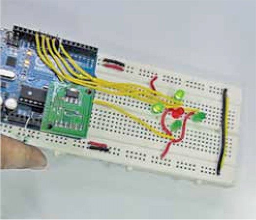
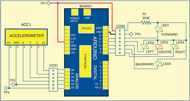
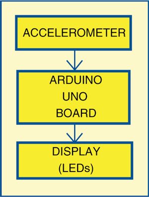
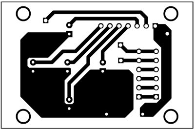
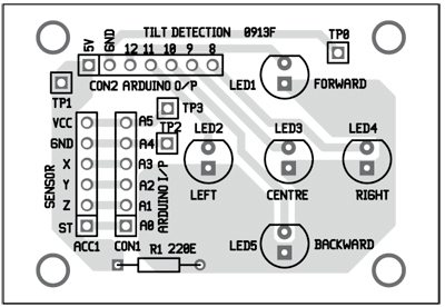
The Arduino-Based Tilt Detector is an embedded sensing system designed to monitor angular position changes using an Arduino Uno microcontroller and an ADXL335 triple-axis accelerometer module. The ADXL335 measures static acceleration due to gravity, as well as dynamic acceleration resulting from motion, and outputs analog voltages proportional to acceleration along the X, Y, and Z axes. These analog voltage signals are fed into the analog input pins of the Arduino Uno, where the onboard analog-to-digital converter (ADC) translates the continuous voltage levels into discrete digital values that the microcontroller can process via software written in the Arduino IDE. As the physical orientation of the single-side PCB changes, the gravitational vector shifts across the accelerometer axes, causing predictable changes in the voltage readings. Based on these calculated angular thresholds, the Arduino evaluates the tilt condition and drives an output array of five LEDs to visually indicate the directional movement or degree of tilt. Connecting wires and specialized connectors ensure reliable electrical continuity between the accelerometer breakout, the microcontroller, and the indicator LEDs mounted on the custom circuit board.
Why Build This
Design a custom analog sensor interface for real-time angular position and motion monitoring on an undergraduate-level engineering platform.
Implement embedded sensor data processing using analog-to-digital conversion to drive discrete visual output indicators like LEDs.
Develop foundational system integration skills applicable to advanced smart solar tracking, tilt control, and structural monitoring applications.
Real-World Application
Tilt detection, obstacle detection, motion inputs, and earthquake sensing.
Skills You'll Learn
Analog-to-digital conversion
accelerometer signal processing
sensor integration
microcontroller GPIO programming
custom PCB wiring
Safety Precautions
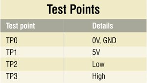
Check correct voltage levels using a test point table during testing to prevent component damage.
Technology Tags
ARDUINO
ACCELEROMETER
ADXL335
PCB
LEDS
SENSORS
Ready to build this?
We stock the boards, sensors and modules this project needs. A full parts list is coming soon — for now, browse our DIY Kits & components or search for Arduino parts.
Frequently Asked Questions
What power supply voltage does the ADXL335 accelerometer require?
The ADXL335 typically operates on 3.3V supplied by the Arduino Uno, so ensure you connect it to the correct power pin to avoid damaging the sensor.
Can I use digital pins instead of analog pins for the accelerometer?
No, the ADXL335 outputs analog voltage signals proportional to acceleration, which must be read using the Arduino's analog input pins.
How do the five LEDs indicate tilt?
The five LEDs act as visual indicators that light up in different combinations or sequences depending on the threshold values calculated from the accelerometer's X and Y axis readings.
Gallery
Kitkraft Project Hub — curated from the maker community, credited at the source.
PRJ-00265