Project Hub/Audio Displays & Interactive Media/Analog Audio & Amplifier Circuits/Audio Equalizer / Tone Control Circuit with Bass, Treble and MID Frequency Control using Op-Amp
Advanced
ANALOG / DISCRETE
₹500 – ₹1,500
3 – 6 Hours
Audio Equalizer / Tone Control Circuit with Bass, Treble and MID Frequency Control using Op-Amp
Design and build an active audio tone control and equalizer circuit powered by a TL072 operational amplifier featuring bass, treble, and mid-frequency controls.
Originally published by Sourav Gupta on CircuitDigest
View original tutorial
How It Works
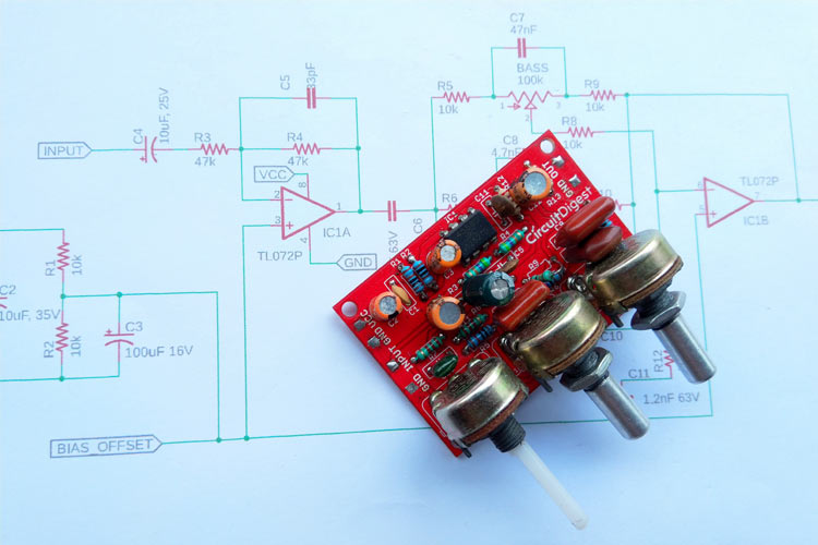
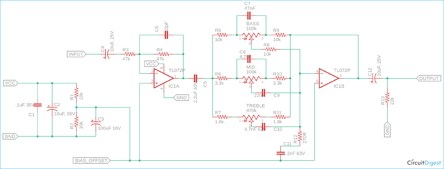
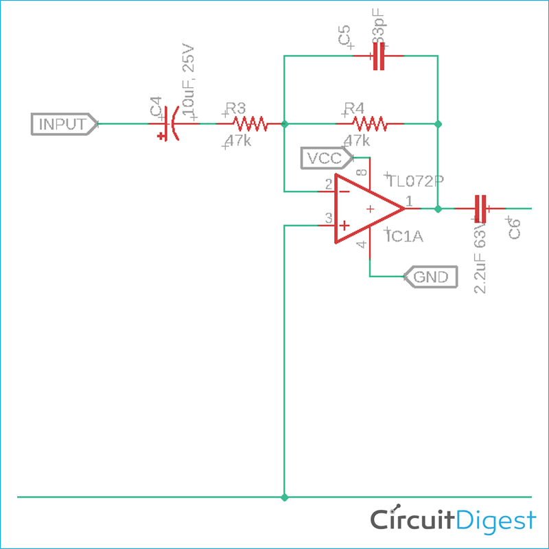
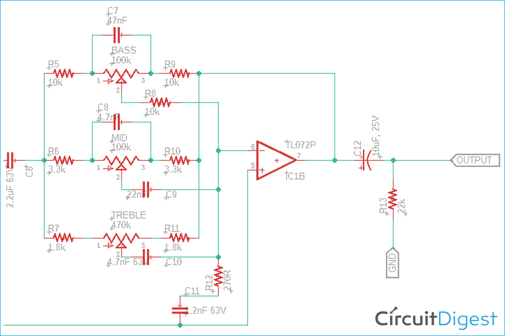
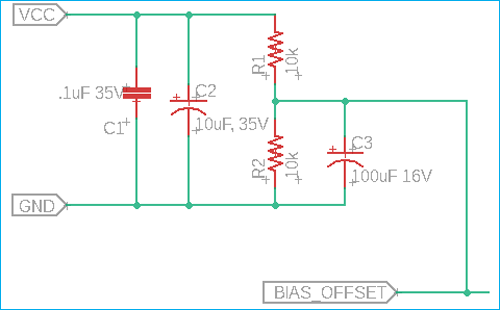
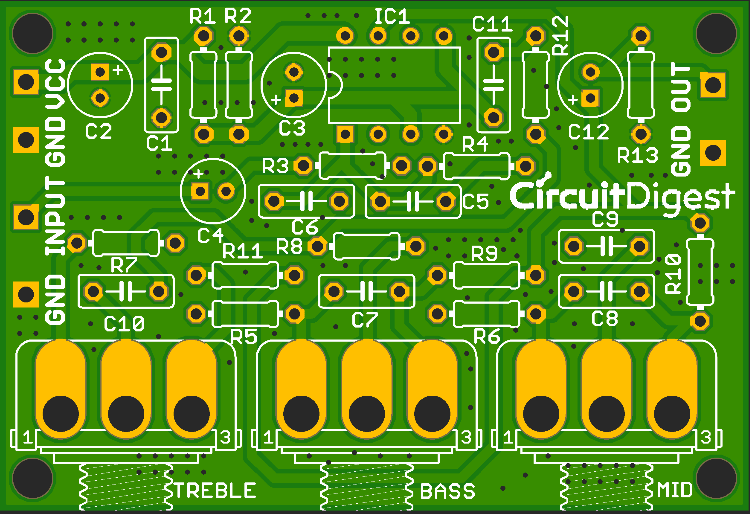
This active audio tone control and equalizer circuit relies on a TL072 operational amplifier (or JRC4558) configured to manipulate specific frequency bands of an incoming audio signal. Powered by a 12V power supply, the circuit utilizes a custom PCB layout designed in Eagle PCB Design Software. The operational amplifier acts as the active gain element, providing signal buffering and amplification while minimizing degradation. Surrounding the op-amp is an intricate network of resistors and capacitors—such as the 100uF, 10uF, 2.2uF, 0.1uF, and various nanofarad and picofarad capacitors—which form frequency-selective filter networks. These filter networks divide the audio spectrum into adjustable bands. Potentiometers, specifically two 100k potentiometers and one 470k potentiometer, serve as the user interface for the bass, treble, and mid-frequency controls. By adjusting the resistance values via these potentiometers, the user alters the feedback loop and frequency response of the op-amp circuit, allowing for precise boost or cut of low, middle, and high frequencies before the audio signal is passed onward to an amplifier system or speaker setup.
Why Build This
Design and optimize active filter networks for multi-band frequency response shaping in undergraduate analog signal processing coursework.
Integrate operational amplifiers into custom preamplifier stages for home theater systems or custom audio mixers.
Gain hands-on PCB layout experience using Eagle PCB Design Software for low-noise analog audio hardware.
Real-World Application
Audio amplifier systems, home theater setups, custom audio mixers, and musical instrument preamplifiers.
Skills You'll Learn
Active filter design
operational amplifier circuit configuration
frequency response shaping
tone control implementation
analog audio preamplifier design
PCB layout with Eagle
Safety Precautions
No specific precautions noted for this build — always follow general electronics safety practices.
Technology Tags
OP-AMP
TL072
ACTIVE FILTER
AUDIO EQUALIZER
TONE CONTROL
PCB DESIGN
ANALOG ELECTRONICS
Ready to build this?
We stock the boards, sensors and modules this project needs. A full parts list is coming soon — for now, browse our DIY Kits & components or search for Analog / Discrete parts.
Frequently Asked Questions
Can I substitute the TL072 operational amplifier with another op-amp?
Yes, the project notes state that a JRC4558 can be used as an alternative, as both are dual operational amplifiers suited for audio applications.
What is the purpose of the 12V power supply in this circuit?
The 12V power supply provides the necessary DC operating voltage for the TL072 operational amplifier to actively process, buffer, and amplify the audio signals.
Why are there different types of capacitors (such as uF, nF, and pF) used in the circuit?
Electrolytic capacitors (like 100uF and 10uF) are typically used for power supply decoupling and bulk filtering, while film and ceramic capacitors (like nanofarad and picofarad values) are deployed in the frequency-selective filter networks to target specific audio bands.
Gallery
Kitkraft Project Hub — curated from the maker community, credited at the source.
PRJ-00238