Project Hub/Audio Displays & Interactive Media/LED Matrix & Cube Displays/Designing a Smartwatch using ESP32 Part 3 - Magnetometer and Gyroscope

Intermediate
ESP32
₹500 – ₹1,500
3 – 6 Hours
Designing a Smartwatch using ESP32 Part 3 - Magnetometer and Gyroscope
Learn how to interface HMC5883L/QMC5883L magnetometer and MPU6050 accelerometer/gyroscope sensors with an ESP32 microcontroller as part of a DIY smartwatch project.
Originally published by Jobit Joseph on CircuitDigest
View original tutorial
How It Works
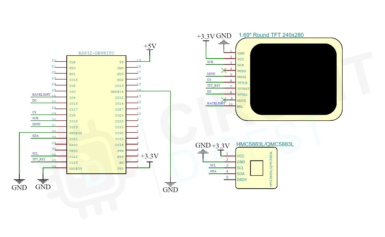
In this project, the ESP32 microcontroller serves as the central processing unit for a DIY smartwatch, gathering data from motion and orientation sensors to display on a TFT screen. The system utilizes the I2C communication protocol via the Wire library to interface with two key sensors: the MPU6050 accelerometer/gyroscope module and the HMC5883L or QMC5883L magnetometer module. The MPU6050 measures acceleration forces and rotational velocity, allowing the device to track dynamic movement, tilts, and orientation changes. Meanwhile, the magnetometer measures Earth's magnetic field to provide compass heading data, acting much like a digital navigation tool. The ESP32 reads these incoming sensor values continuously through its I2C pins. Once processed, the microcontroller formats this orientation and motion data and sends it to the SPI-based TFT display using the TFT_eSPI library. This allows real-time visual feedback of the sensor readings directly on the miniature wearable screen. Power and signal distribution are managed across a breadboard using jumper wires, connecting the sensors and display to the ESP32 DevKit v1 while relying on the Arduino IDE for code compilation and deployment.
Why Build This
Create a custom wearable fitness tracker or digital compass that reacts to your physical movements.
Learn how to integrate multiple I2C and SPI sensors simultaneously into a single microcontroller project.
Build foundational knowledge in inertial measurement units for robotics, drones, and wearable technology.
Real-World Application
Wearable fitness trackers, smartwatches, digital compasses, motion-activated wake-up features, and inertial measurement units for robotics and drones.
Skills You'll Learn
I2C communication protocol
SPI communication protocol
sensor data fusion
motion tracking
display graphics programming
microcontroller pin management
Safety Precautions
Keep magnetic sensors away from strong magnetic materials and stray magnetic fields to ensure accurate compass readings.
Technology Tags
ESP32
HMC5883L
QMC5883L
MPU6050
TFT_ESPI
I2C
SPI
SENSORS
MAGNETOMETER
GYROSCOPE
ACCELEROMETER
SMARTWATCH
WEARABLES
ARDUINO IDE
Ready to build this?
We stock the boards, sensors and modules this project needs. A full parts list is coming soon — for now, browse our DIY Kits & components or search for ESP32 parts.
Frequently Asked Questions
Can I use both the magnetometer and the MPU6050 on the same I2C bus?
Yes, I2C is a communication bus that allows multiple devices to be connected to the same two pins (SDA and SCL), provided they have different hardware addresses.
Why is a TFT display connected via SPI instead of I2C?
TFT displays require high data transfer rates to update graphics smoothly, making SPI a faster and more suitable communication protocol compared to I2C.
What libraries do I need to install in the Arduino IDE to make this work?
You will need the TFT_eSPI library for the display, the DFRobot_QMC5883 library (or equivalent for HMC5883L), along with the built-in Wire.h and SPI.h libraries.
Gallery


Kitkraft Project Hub — curated from the maker community, credited at the source.
PRJ-00642