Project Hub/Test & Measurement Instrumentation/Multimeters, Voltmeters & Ammeters/Digital Ammeter Circuit using PIC Microcontroller and ACS712
Intermediate
PIC
₹500 – ₹1,500
3 – 6 Hours
Digital Ammeter Circuit using PIC Microcontroller and ACS712
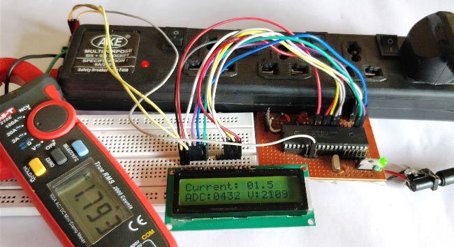
Build a digital ammeter capable of measuring AC and D.C. current from 0 to 30A using a PIC16F877A microcontroller and an ACS712 current sensor.
Originally published by Aswinth Raj on CircuitDigest
View original tutorial
How It Works
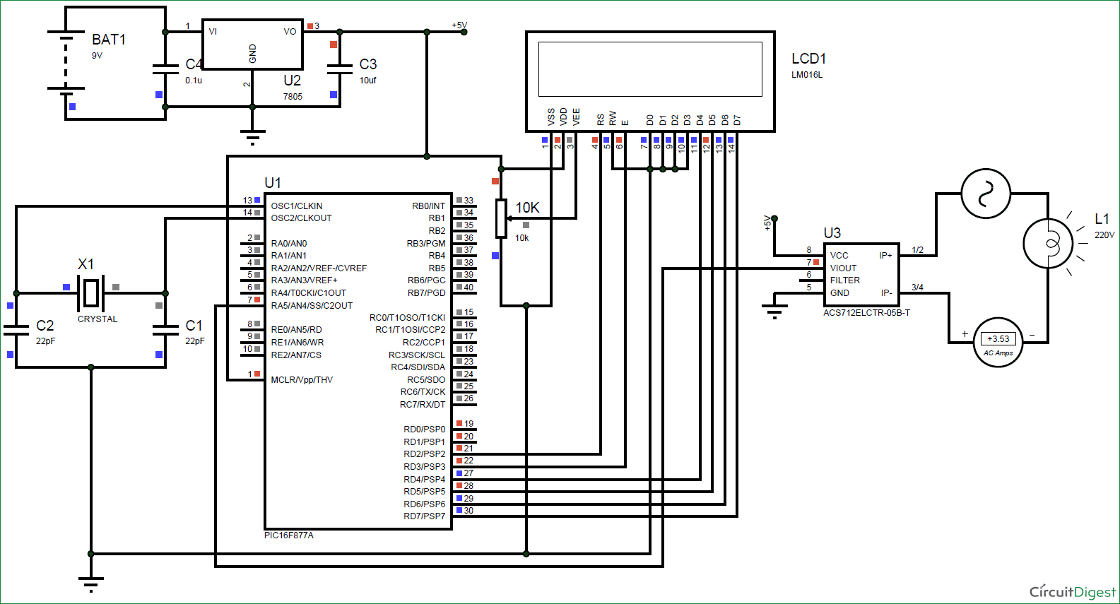
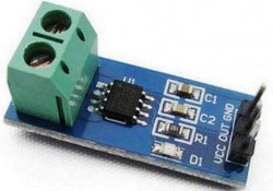
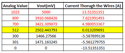
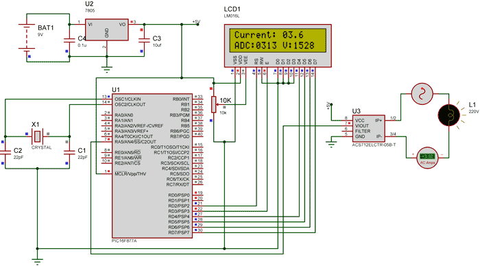
The Digital Ammeter Circuit is designed to measure electrical current by combining analog sensing techniques with digital processing. At the core of the measurement path is the ACS712 current sensor, which utilizes a Hall effect principle to detect current flowing through its internal copper conductor. When current passes through this conductor, it generates a proportional magnetic field that the Hall sensor translates into an analog voltage output. This analog voltage is then fed into the analog-to-digital converter (ADC) channels of the PIC16F877A microcontroller. The microcontroller samples this voltage level, executes internal scaling and calculation algorithms to convert the raw ADC values into actual current units (amperes), and formats the data for visual output. A stable 12V power supply drives the system, regulated down to a clean 5V rail via the 7805 voltage regulator to ensure reliable operation for both the PIC microcontroller and the ACS712 module. Capacitors placed around the voltage regulator and power lines help filter out high-frequency noise and voltage ripples to maintain measurement accuracy. Finally, the processed current data is sent to a 16x2 LCD display, allowing users to read real-time current measurements directly from the hardware setup. The entire system is prototyped using a breadboard or perf board and connecting wires, and its software logic is typically developed and tested using the MPLAB XC8 Compiler and Proteus Simulation Software before hardware deployment.
Why Build This
Design and calibrate custom instrumentation equipment for measuring AC and DC current draw in electrical appliances.
Implement analog-to-digital conversion (ADC) and sensor signal conditioning within a microcontroller architecture for real-time data acquisition.
Develop practical debugging skills for power management systems and electrical load testing within undergraduate engineering applications.
Real-World Application
Measuring and debugging electrical and electronic power systems, monitoring current draw in AC/DC appliances, and developing power management monitoring equipment.
Skills You'll Learn
Microcontroller ADC configuration
Hall-effect current sensing
LCD interfacing
firmware development in C using MPLAB XC8
regulated power supply design
Safety Precautions
Make sure the load does not exceed the maximum rating of the ACS712 module being used and use higher gauge wires for handling high current conductors.
Technology Tags
PIC MICROCONTROLLER
ACS712 CURRENT SENSOR
HALL EFFECT
ADC
LCD DISPLAY
EMBEDDED C
CURRENT MEASUREMENT
Ready to build this?
We stock the boards, sensors and modules this project needs. A full parts list is coming soon — for now, browse our DIY Kits & components or search for PIC parts.
Frequently Asked Questions
Can this circuit measure both AC and DC current?
Yes, the ACS712 sensor is capable of measuring both alternating current (AC) and direct current (DC) depending on the specific module variant and firmware configuration used.
Why is a 7805 voltage regulator necessary in this circuit?
The 7805 voltage regulator steps down the incoming 12V power supply to a stable 5V output, which is required to safely power the PIC16F877A microcontroller and the ACS712 sensor without risking overvoltage damage.
What software tools do I need to program the PIC microcontroller?
You will need the MPLAB XC8 Compiler to write and compile the C code, and optionally Proteus Simulation Software to test the virtual circuit behavior before uploading it to the physical hardware.
Gallery
Kitkraft Project Hub — curated from the maker community, credited at the source.
PRJ-00029