Project Hub/Communication Systems/RF Remote Control Systems/How to build a Simple IR Transmitter and Receiver Circuit using 555 Timer?
Beginner
ANALOG / DISCRETE
< ₹500
3 – 6 Hours
How to build a Simple IR Transmitter and Receiver Circuit using 555 Timer?
A simple wireless infrared communication circuit utilizing a 555 timer IC in astable mode to modulate an IR LED at 38 kHz, paired with a TSOP1738 receiver.
Originally published by J Jayant on CircuitDigest
View original tutorial
How It Works
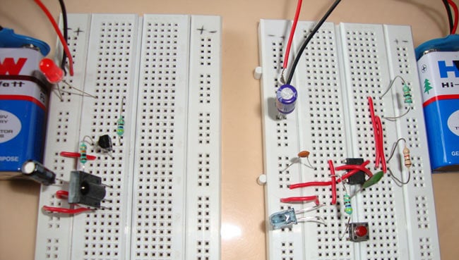
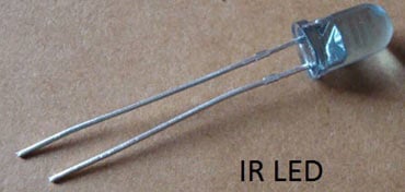
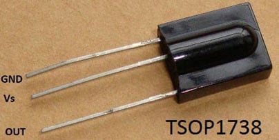
This project creates a wireless infrared communication link divided into a transmitter circuit and a receiver circuit. The transmitter uses a 555 Timer IC configured in astable mode, which means it automatically oscillates to generate a continuous square wave pulse. By selecting appropriate resistors like the 20k and 1k resistors, alongside capacitors such as the 1nF, the timer circuit tunes the output frequency to approximately 38 kHz. This modulated signal drives a BC557 PNP transistor, which switches the IR LED on and off rapidly at that 38 kHz frequency. Modulating the infrared light helps the receiver distinguish the signal from ambient household lighting interference. On the receiving end, the TSOP1738 IR receiver module is specifically tuned to detect 38 kHz infrared signals. When the TSOP1738 senses the pulsed IR light coming from the transmitter, it demodulates the signal and changes its output state. This output can then drive standard LEDs or other indicator components to visually demonstrate successful wireless communication across a short distance, controlled by a simple push button switch powered by the main power supply.
Why Build This
Learn the fundamentals of wireless infrared communication used in everyday consumer electronics like TV and AC remotes.
Understand how to configure a 555 Timer IC in astable mode to generate specific modulation frequencies.
Gain hands-on experience working with specialized receiver modules like the TSOP1738 alongside discrete transistors and LEDs.
Real-World Application
TV remotes, AC remotes, wireless appliance control, and basic remote-controlled automation switches.
Skills You'll Learn
Astable multivibrator configuration
IR signal modulation
transistor switching
basic discrete circuit assembly
optical wireless communication principles
Safety Precautions
No specific precautions noted for this build — always follow general electronics safety practices.
Technology Tags
INFRARED
IR TRANSMITTER
IR RECEIVER
555 TIMER
TSOP1738
ASTABLE MULTIVIBRATOR
BC557 TRANSISTOR
Ready to build this?
We stock the boards, sensors and modules this project needs. A full parts list is coming soon — for now, browse our DIY Kits & components or search for Analog / Discrete parts.
Frequently Asked Questions
Why does the IR LED need to be modulated at 38 kHz instead of just staying constantly turned on?
Modulating the infrared light at a specific frequency like 38 kHz allows the TSOP1738 receiver to filter out steady ambient light sources such as sunlight and indoor incandescent or fluorescent bulbs, preventing false triggers.
Do I need to program any microcontrollers like an Arduino for this project?
No, this is a completely analog, hardware-based circuit utilizing a 555 timer IC and discrete components, so no software or coding is required.
Can I use a different IR receiver instead of the TSOP1738?
It is strongly recommended to use the TSOP1738 because it has an internal filter and demodulator specifically hardcoded to respond to 38 kHz infrared signals, matching the frequency generated by the 555 timer transmitter.
Gallery


Kitkraft Project Hub — curated from the maker community, credited at the source.
PRJ-00008