Project Hub/Artificial Intelligence & Edge ML/Face Recognition & Access Control/Make Your Own Password Locker
Intermediate
OTHER CONTROLLER
₹500 – ₹1,500
3 – 6 Hours
Make Your Own Password Locker
A simple, low-cost, high-security six-digit password-operated locking system built around an ATtiny2313 microcontroller.
Originally published by fayazhassan on ElectronicsForU
View original tutorial
How It Works
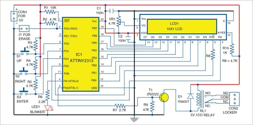
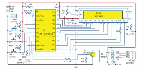
The Make Your Own Password Locker project centers around an ATtiny2313 microcontroller, which serves as the core processing unit for managing security and user interaction. Users interface with the system using three push buttons labeled Up, Right, and Enter to input a secure six-digit password. Visual feedback and system prompts are provided via a 16x2 LCD display, allowing the user to track their input status. When a password is entered, the ATtiny2313 compares the sequence against a stored value in its memory. If the correct code is provided, the microcontroller drives a 2N2222 transistor (T1). Because an AVR microcontroller pin cannot supply enough current to drive an electromechanical relay directly, the 2N2222 transistor acts as a low-side electronic switch. When the base of the transistor receives a high signal from the microcontroller, it allows current to flow through the coil of the 5V single-changeover relay. Activating the relay triggers its internal switch, which can control external locking mechanisms or high-current devices. A blinker LED (LED1) provides visual status indication during operation, such as warning states or successful unlocking events. Additionally, a hardware jumper (J1) is included to facilitate a password reset procedure in case the code needs to be cleared or reconfigured. The entire circuit is powered by a stable DC source and programmed via an AVR Programmer using C software tools like Programmers Notepad.
Why Build This
Develop practical undergraduate-level engineering experience by designing a complete microcontroller-based security system with user interface and actuation elements.
Implement reliable password-protected access control for secure electronic door locks, safe boxes, and restricted-access storage compartments.
Gain hands-on exposure to discrete transistor switching, relay interfacing, and low-level firmware development using AVR microcontrollers.
Real-World Application
Secure electronic door locks, safe boxes, and restricted-access storage compartments.
Skills You'll Learn
AVR microcontroller programming
push-button debouncing and state machine design
16x2 LCD interfacing
transistor-based relay switching
hardware reset mechanism implementation
Safety Precautions
Ensure proper DC power supply ratings (5V DC, 300mA or above) and handle electromechanical relay connections carefully.
Technology Tags
AVR
ATTINY2313
MICROCONTROLLER
LCD DISPLAY
RELAY
SECURITY SYSTEM
EEPROM
C PROGRAMMING
Ready to build this?
We stock the boards, sensors and modules this project needs. A full parts list is coming soon — for now, browse our DIY Kits & components or search for Other Controller parts.
Frequently Asked Questions
How do I reset the password if I forget it?
You can use the designated jumper (J1) on the circuit board to execute a password reset procedure as designed in the system firmware.
Can I connect a heavy electronic door lock directly to the ATtiny2313 output?
No, the microcontroller pins cannot provide enough current to drive a lock directly. The ATtiny2313 controls a 2N2222 transistor, which safely switches the 5V single-changeover relay to handle external loads.
What software do I need to program the ATtiny2313?
You can use Programmers Notepad with WinAVR or any standard AVR C compiler to write and compile the code, along with AVR flashing software to upload the hex file via an AVR programmer.
Gallery

Kitkraft Project Hub — curated from the maker community, credited at the source.
PRJ-00244