Project Hub/Basic Analog & Power Electronics/Power Supplies & Voltage Regulators/Matrix Keypad Embedded-C Driver For A Microcontroller
Intermediate
8051
₹500 – ₹1,500
3 – 6 Hours
Matrix Keypad Embedded-C Driver For A Microcontroller
Learn how to develop both polled and interrupt-driven matrix keypad device drivers in embedded-C for 8-bit microcontrollers like the AT89S52.
Originally published by N Abid Ali Khan on ElectronicsForU
View original tutorial
How It Works
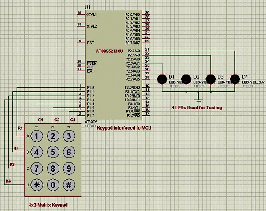
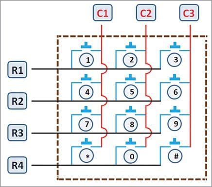
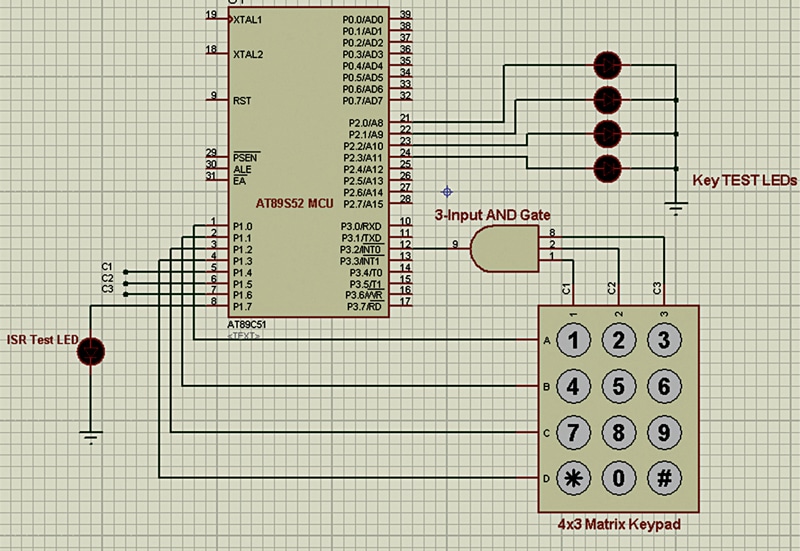
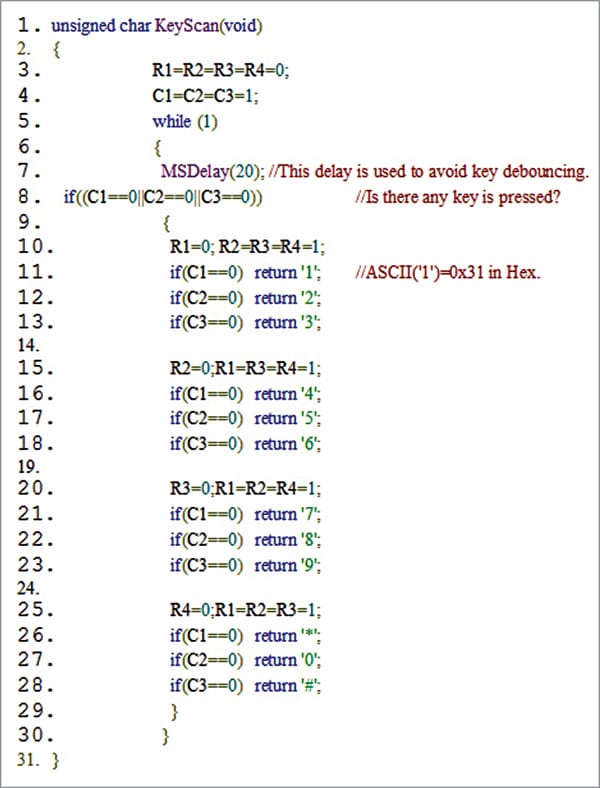
The Matrix Keypad Embedded-C Driver project interfaces an AT89S52 microcontroller with a matrix keypad and an optional JHD162A 2x16 LCD to capture and display user input. A matrix keypad organizes tactile switches into rows and columns, drastically reducing the number of microcontroller pins needed compared to individual push buttons. The AT89S52 scans the keypad by systematically driving its output lines—typically configured as rows—either low or high, while reading the input lines configured as columns. When a user presses a key, it creates a closed electrical connection between a specific row and column. By detecting which column changes state in response to the driven row, the embedded-C firmware identifies the exact key pressed. To ensure reliable performance, the driver software accounts for mechanical switch bounce, utilizing delay loops or timer-based debouncing routines. Depending on the implemented driver architecture, the system either continuously polls the keypad within the main execution loop or uses external interrupts to detect keystrokes asynchronously. Once a valid key press is recognized, the microcontroller can process the input, perform internal logic, and optionally route the corresponding character or code to the JHD162A LCD for visual feedback. The entire hardware setup relies on a stable power supply and appropriate pull-up or pull-down configurations to maintain reliable logic levels across all general-purpose input/output pins.
Why Build This
Master low-level hardware abstraction by writing custom embedded-C device drivers for standard human-interface peripherals.
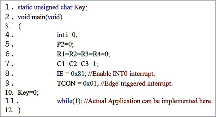
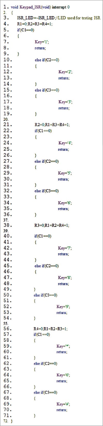
Understand the performance and architectural trade-offs between polled and interrupt-driven input processing in resource-constrained 8-bit microcontrollers.
Gain practical experience integrating multiplexed matrix hardware alongside character LCD displays for standalone embedded instrumentation.
Real-World Application
Used in embedded systems and consumer appliances requiring reliable user input interfaces alongside background communication or sensor data processing.
Skills You'll Learn
Embedded-C driver development
GPIO multiplexing
keypad scanning algorithms
switch debouncing techniques
character LCD interfacing
interrupt-driven programming
Safety Precautions
No specific precautions noted for this build — always follow general electronics safety practices.
Technology Tags
EMBEDDED-C
MICROCONTROLLER
KEYPAD DRIVER
INTERRUPTS
C51
KEIL UVISION
PROTEUS
Ready to build this?
We stock the boards, sensors and modules this project needs. A full parts list is coming soon — for now, browse our DIY Kits & components or search for 8051 parts.
Frequently Asked Questions
What is the difference between polled and interrupt-driven keypad scanning?
Polling requires the microcontroller to constantly check the keypad state within the main program loop, whereas interrupt-driven scanning allows the CPU to execute other tasks and only respond to keystrokes when an electrical change triggers an interrupt.
Why do I need to debounce the keypad switches in software?
Mechanical switches physically bounce when pressed, causing microscopic electrical fluctuations that a fast microcontroller might misinterpret as multiple rapid key presses. Debouncing ensures each physical press is registered accurately as a single event.
Can I use this project without the optional JHD162A 2x16 LCD?
Yes, the LCD is strictly optional for visual feedback; the microcontroller can still process the key press data for internal logic, serial transmission, or debugging within the Keil simulation environment.
Gallery
Kitkraft Project Hub — curated from the maker community, credited at the source.
PRJ-00610