This project is sourced from another site, not written by us — this list is our best match of their components against what we stock, not a verified bill of materials. Always check the original blog (linked above) for the actual parts list before buying.
This list includes a generic resistor set
as a placeholder — it is not matched to the exact value or part number this circuit needs. The correct one is specified on the original source page linked above; check it before buying.
We don't carry yet: LCD (generic / unspecified)
PIC Microcontroller
Transistors (BC547 / 2N2222 / TIP / MOSFET)
Transformer
Diodes (1N4007 / 1N4148 / Schottky / Zener)
Voltage Regulator IC (7805 / LM317 / 1117)
Header Pins / Terminals / Connectors
Capacitors
driver
and connecting components
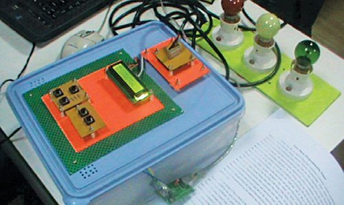
The Programmable Interval Timer is built around a PIC16F877A microcontroller (IC3), which acts as the central processing unit for timing control and logic operations. Power is supplied to the system via a 230V AC primary to 15V 500mA secondary transformer (X1) that steps down the mains voltage. The alternating current is converted to direct current by a bridge rectifier module (BR1) and smoothed using filtering capacitors. To ensure stable operation for the logic circuitry, this voltage is stepped down and regulated in two stages: a 7812 regulator IC (IC1) providing a 12V rail and a 7805 regulator IC (IC2) supplying a clean 5V DC rail for the microcontroller and display. User interaction and visual feedback are handled by a 16x2 LCD (LCD1), which presents performance timing data in real time. The microcontroller uses three BC547 transistors (T1, T2, T3) as solid-state switches to drive peripheral indicators or control signals based on the active timer states. Additionally, the system features a COM port DB9 connector paired with a MAX232 converter/driver (IC4). The MAX232 translates the TTL-level UART signals from the PIC16F877A microcontroller into RS-232 voltage levels, enabling reliable serial communication with an external computer running a Visual Basic program and MS Access database for logging and programming event intervals.
Why Build This
Design and implement a reliable timing instrument tailored for inter-college, inter-zonal, and inter-university stage shows, cultural events, and competitions to manage contestant timing accurately and avoid disputes.
Gain practical experience integrating microcontroller firmware with desktop software environments by establishing serial communication between a PIC MCU and a Visual Basic application backed by an MS Access database.
Construct a complete linear regulated power supply circuit that safely steps down 230V AC mains voltage to power sensitive digital logic and display components.
Real-World Application
Used in inter-college, inter-zonal, and inter-university stage shows, cultural events, and competitions to manage contestant timing accurately and avoid disputes.
Skills You'll Learn
Microcontroller firmware development
linear power supply design
RS-232 serial communication interfacing
transistor-based load switching
alphanumeric LCD integration
database-backed application integration
Safety Precautions
Exercise standard electrical caution when working with the 230V AC primary to 15V transformer and power supply circuits.
Technology Tags
MICROCONTROLLER
PIC16F877A
LCD
MAX232
TIMER
SERIAL COMMUNICATION
VISUAL BASIC
MS ACCESS
Frequently Asked Questions
The PIC microcontroller communicates using TTL logic levels (0V and 5V), whereas standard computer COM ports use RS-232 voltage levels (which can range from -15V to +15V). The MAX232 converter translates these voltage levels so the hardware communicates safely and reliably without damaging the microcontroller.
No, standard 16x2 LCD modules require a 5V supply for their logic and controller operations. Connecting them to a 12V rail will permanently damage the display; it must be powered from the 5V output provided by the 7805 regulator IC (IC2).
The Visual Basic program communicates with the PIC16F877A microcontroller over a serial link via the DB9 connector and MAX232 driver, allowing the computer to send configuration parameters, receive timer events, and log data into an MS Access database.
Gallery
This page is part of Kitkraft's Project Hub — a curated collection of electronics & robotics projects gathered from the maker community to help students and hobbyists discover and learn to build. Kitkraft does not claim authorship of the original project, and makes no representation as to the accuracy, completeness or safety of third-party source material. The summary and "How It Works" explanation above are AI-generated, rewritten with reference to the original tutorial — not a reproduction of it. Full credit and a direct link to the original source are provided above. If you're the original creator and have a concern about how your work is represented here, please contact us and we'll address it promptly.
 USB to UART/ESP8266 Adapter Programmer for ESP-01 WiFi Modules with CH340G Chip
Rs. 99.00
 10pcs - 220 ohm 1/4 W Resistor Set
Rs. 39.00
 400 Points Mini Solderless Prototype PCB Breadboard High Quality
Rs. 89.00
 MB102 Adjustable Breadboard Power Supply Module (3.3V & 5V) for Arduino & Raspberry Pi
Rs. 139.00
 Jumper Wire 10 Pin Male To Male 20cm
Rs. 45.00
 Jumper Wire 10 Pin Male To Female 20cm
Rs. 45.00


