This project is sourced from another site, not written by us — this list is our best match of their components against what we stock, not a verified bill of materials. Always check the original blog (linked above) for the actual parts list before buying.
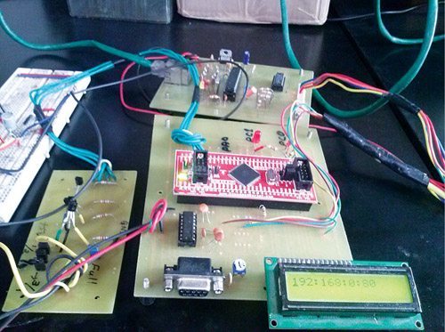
The Web-Based Water-Level Monitor and Pump Controller is an embedded system designed to track fluid levels and manage a motorized pump automatically or through a web interface. At the heart of the system is the ATmega128 microcontroller module (IC1), which serves as the central processing unit responsible for executing the control logic. Five water-level sensors are positioned at various heights within the tank to provide discrete digital inputs representing the current volume of water. The microcontroller reads these sensor states and updates a local 16x2 LCD display to give users a direct visual readout of the water level. For network connectivity, the system utilizes an ENC28J60 Ethernet controller module (IC2), allowing the microcontroller to communicate over a local network. Because the ATmega128 typically operates at 5V logic while the ENC28J60 Ethernet module operates at 3.3V, a 74HCT125 level shifter IC (IC3) is integrated into the circuit to safely bridge the voltage difference for digital signals without causing hardware damage. When the water drops below a certain threshold or a remote web command is received, the ATmega128 triggers a motor pump control relay circuit. This relay acts as an electrically isolated switch, enabling the low-voltage microcontroller to safely control the high-current power supply needed to turn the water pump on or off.
Why Build This
Gain hands-on experience building automated systems for residential or agricultural water tanks to prevent overflows and dry running.
Learn how to integrate microcontrollers with wired Ethernet modules to create interactive, web-accessible IoT devices.
Understand how to safely interface digital components operating at different logic voltage levels using dedicated level shifters.
Real-World Application
Remote monitoring and automated control of overhead water tanks in residential, commercial, and agricultural settings to prevent overflows and dry running of pumps.
Skills You'll Learn
microcontroller programming
digital sensor integration
relay-based motor control
LCD interfacing
Ethernet network communication
voltage level shifting
Safety Precautions
Ensure correct level-shifting between the 5V ATmega128 microcontroller and the 3.3V ENC28J60 Ethernet controller to prevent damage to components.
Technology Tags
AVR
ATMEGA128
ETHERNET CONTROLLER
ENC28J60
TCP/IP
SPI
C PROGRAMMING
EMBEDDED SYSTEMS
IOT
WATER LEVEL MONITOR
MOTOR PUMP CONTROLLER
Frequently Asked Questions
The ATmega128 microcontroller typically operates on 5V logic, whereas the ENC28J60 Ethernet controller operates on 3.3V. The 74HCT125 level shifter safely converts signal voltages between the two ICs to prevent damaging the lower-voltage Ethernet module.
Five water-level sensors placed at different heights inside the tank send real-time status signals to the ATmega128 microcontroller, which evaluates the water volume and activates the motor pump control relay accordingly.
The project uses the AVR-GCC compiler to write, build, and compile the C code for the ATmega128 microcontroller before uploading it to the board.
Gallery
This page is part of Kitkraft's Project Hub — a curated collection of electronics & robotics projects gathered from the maker community to help students and hobbyists discover and learn to build. Kitkraft does not claim authorship of the original project, and makes no representation as to the accuracy, completeness or safety of third-party source material. The summary and "How It Works" explanation above are AI-generated, rewritten with reference to the original tutorial — not a reproduction of it. Full credit and a direct link to the original source are provided above. If you're the original creator and have a concern about how your work is represented here, please contact us and we'll address it promptly.
 5V 1 Channel Relay Module
Rs. 87.00
 Jumper Wire 10 Pin Male To Male 20cm
Rs. 45.00
 MB102 Adjustable Breadboard Power Supply Module (3.3V & 5V) for Arduino & Raspberry Pi
Rs. 139.00
 400 Points Mini Solderless Prototype PCB Breadboard High Quality
Rs. 89.00
 Jumper Wire 10 Pin Male To Female 20cm
Rs. 45.00


