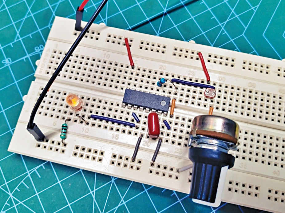
This DIY project demonstrates how to build a basic hobby-level Voltage-to-Frequency Converter (VFC) using the HEF4046B CMOS micropower phase-locked loop IC.
This project is sourced from another site, not written by us — this list is our best match of their components against what we stock, not a verified bill of materials. Always check the original blog (linked above) for the actual parts list before buying.
This list includes a generic resistor set
as a placeholder — it is not matched to the exact value or part number this circuit needs. The correct one is specified on the original source page linked above; check it before buying.
We don't carry yet: Microcontroller IC (DIP) / Chip
Capacitors
Potentiometer / Trimpot
LED1 (red
amber)
This circuit operates as a basic Voltage-to-Frequency Converter (VFC) centered around the HEF4046B CMOS micropower phase-locked loop integrated circuit. While the HEF4046B is frequently used for phase-locking applications, its internal voltage-controlled oscillator (VCO) section can be isolated and utilized independently for frequency conversion. An incoming DC control voltage—which can be manually adjusted using an optional 100k linear potentiometer (VR1) across a 10k resistor (R1)—is applied to the VCO input pin of the IC. The magnitude of this analog input voltage dictates the internal charging and discharging current for an external timing capacitor, which in this design is a 100nF capacitor (C1) connected to the appropriate oscillator terminals of the HEF4046B. As the input voltage increases, the rate at which the capacitor charges and discharges changes proportionally, driving the VCO to output a square wave pulse train whose frequency directly mirrors the applied voltage level. An optional red or amber LED1 can be incorporated into the output stage to provide visual confirmation of the pulsing frequency. Additionally, an optional filter capacitor (C2) can be placed across the power rails or input lines to help suppress noise and stabilize the DC supply. Operating from a regulated 5V DC power source, the entire circuit can be easily prototyped on a standard breadboard and monitored using an oscilloscope to observe real-time frequency modulation as the input voltage varies.
Why Build This
Gain practical undergraduate-level experience in translating analog DC voltage domains into digital frequency domains for robust data transmission.
Learn to characterize and test active integrated circuits like the HEF4046B phase-locked loop by isolating and utilizing internal functional blocks such as the voltage-controlled oscillator.
Master the use of an oscilloscope to visually analyze signal characteristics, frequency shifts, and waveform responses relative to varying input parameters.
Real-World Application
Transmitting analog sensor signals over long distances without interference via optical, coaxial, or radio links by converting them into frequency signals.
Skills You'll Learn
Voltage-to-frequency conversion
VCO operation
phase-locked loop architecture
oscilloscope signal analysis
breadboard prototyping
analog signal conditioning
Safety Precautions
A well-regulated 5V DC power source is necessary to run the VFC circuit safely and correctly.
Technology Tags
HEF4046B
CMOS
PLL
VOLTAGE-TO-FREQUENCY CONVERTER
VFC
OSCILLOSCOPE
BREADBOARD
ANALOG ELECTRONICS
VCO
Frequently Asked Questions
While a multimeter with a frequency counter function can measure the output frequency, an oscilloscope is strongly recommended because it allows you to visualize the actual waveform shape, duty cycle, and real-time frequency changes as you adjust the input voltage.
Voltage-to-frequency converters rely heavily on stable supply voltages to ensure that the internal oscillator's timing currents remain consistent. Any voltage fluctuations from an unregulated supply would introduce error and noise into the output frequency.
The 100nF capacitor acts as the primary timing component for the HEF4046B's internal voltage-controlled oscillator, setting the baseline frequency range alongside the input voltage.
Gallery
This page is part of Kitkraft's Project Hub — a curated collection of electronics & robotics projects gathered from the maker community to help students and hobbyists discover and learn to build. Kitkraft does not claim authorship of the original project, and makes no representation as to the accuracy, completeness or safety of third-party source material. The summary and "How It Works" explanation above are AI-generated, rewritten with reference to the original tutorial — not a reproduction of it. Full credit and a direct link to the original source are provided above. If you're the original creator and have a concern about how your work is represented here, please contact us and we'll address it promptly.
 10pcs - 220 ohm 1/4 W Resistor Set
Rs. 39.00
 MB102 Adjustable Breadboard Power Supply Module (3.3V & 5V) for Arduino & Raspberry Pi
Rs. 139.00
 Jumper Wire 10 Pin Male To Male 20cm
Rs. 45.00
 400 Points Mini Solderless Prototype PCB Breadboard High Quality
Rs. 89.00
 Jumper Wire 10 Pin Male To Female 20cm
Rs. 45.00


