Project Hub/Communication Systems/RF Remote Control Systems/Build A Gesture And Clap Controlled Robot
Beginner
ARDUINO
₹1,500 – ₹5,000
6 – 12 Hours
Build A Gesture And Clap Controlled Robot
A two-in-one robot project that can be controlled in four directions either by clapping sounds or through simple hand gestures using an accelerometer and RF wireless communication.
Originally published by Sani Theo on ElectronicsForU
View original tutorial
How It Works
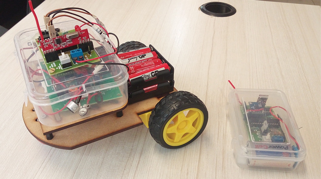
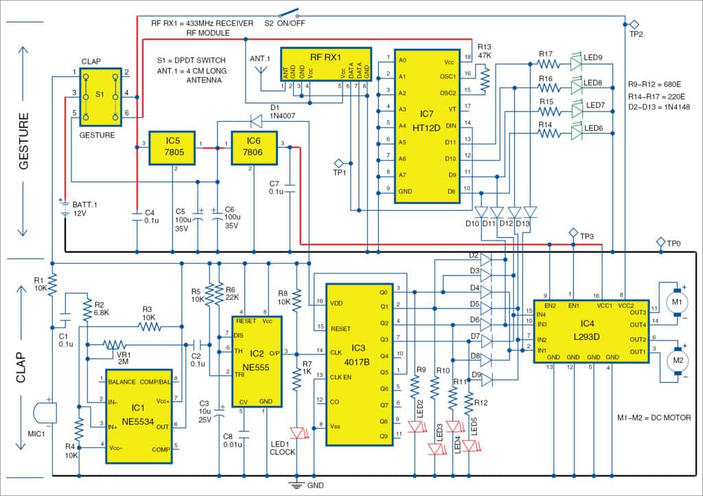
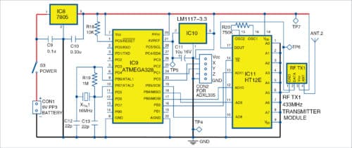
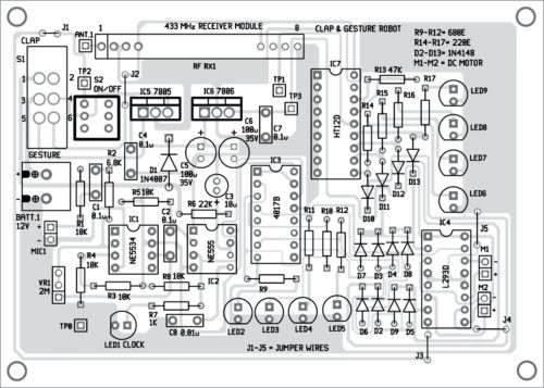
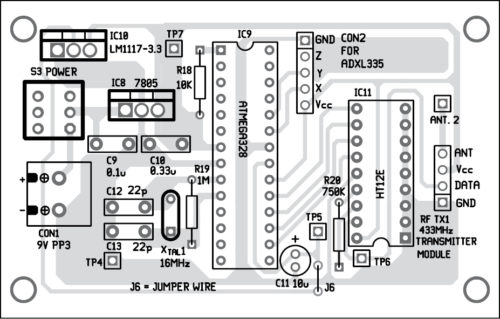
The Gesture and Clap Controlled Robot is an interactive dual-mode mobile platform powered by an Arduino Uno featuring an ATmega328P microcontroller. In the acoustic control mode, an electret condenser microphone (MIC1) captures sound waves like claps. The analog audio signal is amplified by an NE5534 operational amplifier (IC1), processed alongside an NE555 timer (IC2) and a 4017B decade counter (IC3) to detect distinct acoustic patterns, which signal the microcontroller to trigger robot movement. Alternatively, the gesture control mode uses an accelerometer to detect physical tilting and hand movements. This directional data is transmitted wirelessly via RF transmitter and receiver modules to the main board. Once the microcontroller interprets the input commands from either the acoustic or RF wireless pathway, it sends control signals to the L293D motor driver (IC4). The motor driver supplies the necessary current and switching logic to drive the DC motors (M1 and M2) forward, backward, left, or right. Additional passive components, diodes, resistors, presets, and LEDs support circuit stability, signal conditioning, and visual status indication throughout operation.
Why Build This
Gain practical, hands-on experience combining analog sound detection with digital microcontroller processing for real-world robotics.
Learn how to integrate wireless RF modules and accelerometers to implement remote gesture control systems suitable for assistive technology.
Develop foundational troubleshooting skills by wiring multiple discrete integrated circuits, including op-amps, timers, counters, and motor drivers.
Real-World Application
Assistive robotics, hands-free appliance or wheelchair control, interactive educational toys, and gesture-based human-machine interfaces.
Skills You'll Learn
Audio signal amplification
RF wireless communication
accelerometer data interpretation
motor driver interfacing
decade counter logic
timer circuit configuration
Safety Precautions
No specific precautions noted for this build — always follow general electronics safety practices.
Technology Tags
ROBOTICS
ACCELEROMETER
RF WIRELESS
SOUND SENSOR
NE555
ATMEGA328P
MOTOR DRIVER
MICROCONTROLLER
Ready to build this?
We stock the boards, sensors and modules this project needs. A full parts list is coming soon — for now, browse our DIY Kits & components or search for Arduino parts.
Frequently Asked Questions
Can I use both the clap control and the gesture control at the exact same time?
Typically, the system is designed to process one control mode at a time to prevent conflicting movement commands from being sent to the motor driver.
What is the purpose of the NE5534 op-amp in the microphone circuit?
The op-amp amplifies the very weak electrical signals produced by the electret condenser microphone when it picks up sound, making the audio signal strong enough for the rest of the control logic to process.
Do I need to write complex software to make this robot work?
No software is listed as required for this specific build, as the control logic heavily relies on hardware-based components like the 4017B decade counter, NE555 timer, and RF modules to interface directly with the motor driver.
Gallery
Kitkraft Project Hub — curated from the maker community, credited at the source.
PRJ-00182