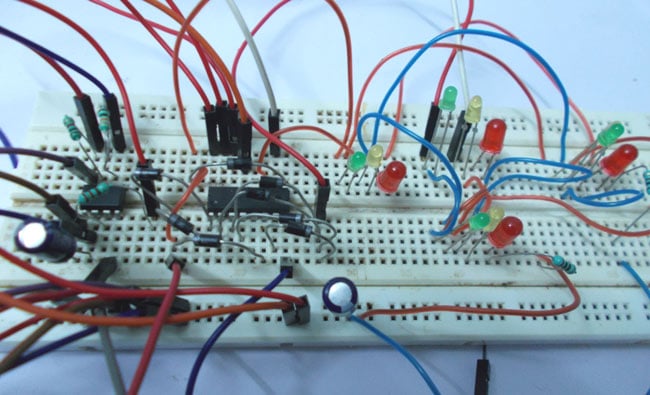
Four Way Traffic Lights Circuit using 555 Timer IC
A classic analog electronics project that controls a four-way traffic light intersection using a 555 Timer IC as a clock pulse generator and a CD4017 decade counter.
We stock the boards, sensors and modules this project needs. A full parts list is coming soon — for now, browse our DIY Kits & components or search for Analog / Discrete parts.
The Four Way Traffic Lights Circuit operates using a combination of a 555 Timer IC and a CD4017 decade counter to create a sequential timing system. First, the 555 Timer IC is configured in an astable mode to act as a steady clock pulse generator, continuously outputting a train of square wave pulses. These timing pulses are then fed into the clock input of the CD4017 decade counter. As the counter receives each pulse, it sequentially steps its active output from one pin to the next in a repeating cycle. By connecting diodes and LEDs to the various output pins of the counter, the circuit routes current to specific colored indicator lights at different steps in the sequence. This ensures that the traffic lights change in a predetermined, timed order, mimicking a real-world four-way intersection controller entirely through analog and digital sequential logic without needing any programmable microcontrollers.
Why Build This
Learn how timing pulses from a 555 timer can drive sequential logic circuits like the CD4017 counter.
Visualize electronic signals turning into real-world actions by controlling LEDs that mimic actual traffic lights.
Gain hands-on experience building an autonomous analog system without needing to write any computer code.
Ensure correct polarity when connecting DC power supplies and electrolytic capacitors to prevent damage.
Technology Tags
555 TIMER
CD4017 DECADE COUNTER
LEDS
DIODES
ANALOG CIRCUITS
TIMING CIRCUITS
Frequently Asked Questions
No, this is a purely hardware-based analog and digital logic project using integrated circuits, so no software or programming is required.
The 555 Timer acts as the clock generator, producing a continuous stream of electrical pulses that dictate the speed at which the traffic lights change.
Yes, by changing the values of the resistors and capacitors connected to the 555 Timer, you can alter the timing interval of the clock pulses.
Gallery
This page is part of Kitkraft's Project Hub — a curated collection of electronics & robotics projects gathered from the maker community to help students and hobbyists discover and learn to build. Kitkraft does not claim authorship of the original project, and makes no representation as to the accuracy, completeness or safety of third-party source material. The summary and "How It Works" explanation above are AI-generated, rewritten with reference to the original tutorial — not a reproduction of it. Full credit and a direct link to the original source are provided above. If you're the original creator and have a concern about how your work is represented here, please contact us and we'll address it promptly.