How to use Digital-to-Analog Converter (DAC) with STM32F10C8 Board
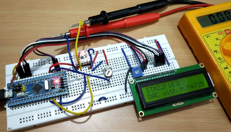
This project demonstrates how to use the MCP4725 Digital-to-Analog Converter module with an STM32F103C8 (Blue Pill) board, reading input voltages via ADC and displaying both input and output values on a 16x2 LCD.
This project is sourced from another site, not written by us — this list is our best match of their components against what we stock, not a verified bill of materials. Always check the original blog (linked above) for the actual parts list before buying.
This project integrates an STM32F103C8 microcontroller (commonly known as the Blue Pill) with an MCP4725 Digital-to-Analog Converter (DAC) IC to process and generate signals for a smart pill dispenser system. The circuit centers around a 10k potentiometer connected to an analog input on the STM32 board. As the potentiometer's wiper position changes, it varies the input voltage, which the microcontroller reads via its internal Analog-to-Digital Converter (ADC). The STM32 processes this numerical value and communicates with the MCP4725 DAC module using the I2C protocol. The MCP4725 then converts this digital data back into a precise analog output voltage. Simultaneously, the system updates a 16x2 LCD display using the LiquidCrystal library to show both the input voltage read by the ADC and the resulting output generated by the DAC. By leveraging the Wire and SoftWire libraries within the Arduino IDE, the STM32 manages both the I2C peripheral communication and the parallel interface required by the LCD. This setup allows undergraduates to observe how digital systems bridge the gap between physical user inputs—such as adjusting a dosage control knob—and analog actuation, which is essential for regulating mechanical components like dispenser motors or providing variable reference voltages in biomedical assistive devices.
Why Build This
Design precise analog control systems required for regulating motor speeds and dispensing mechanisms in smart medical devices.
Master the implementation of external I2C DAC modules to expand the analog output capabilities of resource-constrained microcontrollers.
Develop real-time data acquisition and visualization interfaces using an STM32 board and an LCD display.
Real-World Application
Used in motor control speed regulation, LED brightness dimming, audio amplifiers, video encoders, and data acquisition systems.
Skills You'll Learn
I2C communication protocol
Analog-to-Digital conversion
Digital-to-Analog conversion
LCD interfacing
potentiometer signal conditioning
Arduino IDE library integration
Safety Precautions
No specific precautions noted for this build — always follow general electronics safety practices.
Technology Tags
STM32
DAC
MCP4725
I2C
ADC
LCD DISPLAY
POTENTIOMETER
C++
ARDUINO IDE
Frequently Asked Questions
While the STM32F103C8 has ADCs (Analog-to-Digital Converters) to read voltages, it lacks a true built-in DAC on this specific model to reliably output smooth variable analog voltages, necessitating the external MCP4725 IC.
Yes, by setting up the Arduino IDE with the appropriate STM32 board package, you can utilize standard and compatible libraries like Wire and LiquidCrystal for I2C and display management.
The 10k potentiometer acts as a manual voltage divider, providing a variable analog input voltage to simulate sensor data or user inputs for the smart pill dispenser application.
Gallery
This page is part of Kitkraft's Project Hub — a curated collection of electronics & robotics projects gathered from the maker community to help students and hobbyists discover and learn to build. Kitkraft does not claim authorship of the original project, and makes no representation as to the accuracy, completeness or safety of third-party source material. The summary and "How It Works" explanation above are AI-generated, rewritten with reference to the original tutorial — not a reproduction of it. Full credit and a direct link to the original source are provided above. If you're the original creator and have a concern about how your work is represented here, please contact us and we'll address it promptly.
 MB102 Adjustable Breadboard Power Supply Module (3.3V & 5V) for Arduino & Raspberry Pi
Rs. 139.00
 Jumper Wire 10 Pin Male To Male 20cm
Rs. 45.00
 400 Points Mini Solderless Prototype PCB Breadboard High Quality
Rs. 89.00
 Jumper Wire 10 Pin Male To Female 20cm
Rs. 45.00


