Project Hub/Audio Displays & Interactive Media/LED Matrix & Cube Displays/LED Light For Bikes To Improve Visibility
Beginner
ATTINY85
₹500 – ₹1,500
3 – 6 Hours
LED Light For Bikes To Improve Visibility
An inexpensive and easy-to-make LED bike headlight featuring both a steady glow and an adjustable strobe light option to improve road visibility.
Originally published by T.K. Hareendran on ElectronicsForU
View original tutorial
How It Works
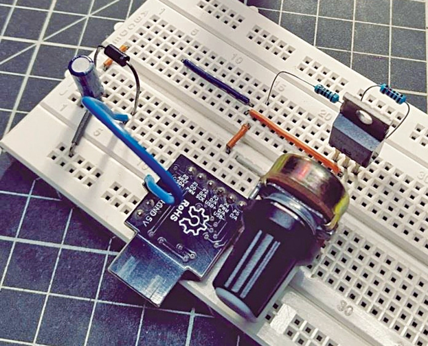
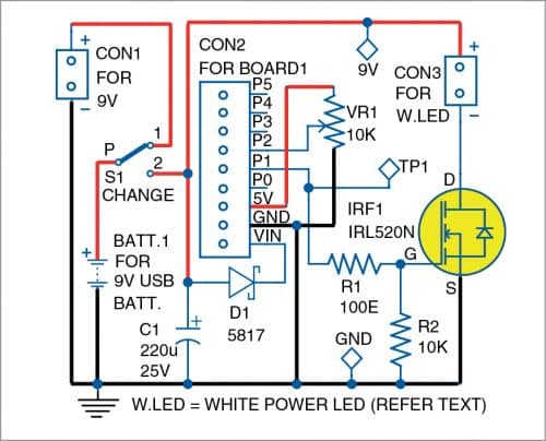
The core of this bicycle visibility system is the Digispark ATtiny85 microcontroller board, which acts as the central processing unit to control the lighting modes. Power is supplied by a 9V USB rechargeable battery connected via a 2-pin connector, with a 220µF electrolytic capacitor placed across the power rails to help stabilize voltage fluctuations. To drive the high-power 1-watt star white LEDs safely without overloading the microcontroller's limited digital output current capacity, an IRL520N N-channel MOSFET is employed as an electronic switch. The ATtiny85 sends control signals to the gate of the MOSFET, utilizing a 10k resistor as a pull-down and a 100-ohm resistor for gate current limiting to protect the I/O pins from high inrush currents caused by MOSFET gate capacitance. A 10k potentiometer is integrated into the circuit as an analog input device, allowing the microcontroller to read varying voltage levels and dynamically adjust the operational state between a steady beam and an adjustable strobe lighting pattern.
Why Build This
Design and implement a practical power-switching circuit using a MOSFET to drive high-wattage LEDs from a low-power microcontroller.
Utilize analog-to-digital conversion by interfacing a potentiometer to dynamically control lighting output frequencies or modes.
Deploy a functional, microcontroller-based safety device optimized for low-visibility cycling conditions.
Real-World Application
Mounted on bicycles as a headlight to ensure the rider is visible to other vehicles and pedestrians at night or in foggy conditions, while also providing enough illumination to see obstacles on the road.
Skills You'll Learn
MOSFET power switching
microcontroller I/O interfacing
analog sensor reading with potentiometers
LED driver circuit design
power supply decoupling
Safety Precautions
Ensure correct polarity when connecting the battery. Use appropriate gate resistors (R1 and R2) to protect the microcontroller I/O pins from high inrush currents originating from the MOSFET gate capacitance.
Technology Tags
MICROCONTROLLER
ATTINY85
LED
STROBE LIGHT
MOSFET
POWER REGULATION
POTENTIOMETER
BIKE LIGHTING
Ready to build this?
We stock the boards, sensors and modules this project needs. A full parts list is coming soon — for now, browse our DIY Kits & components or search for ATtiny85 parts.
Frequently Asked Questions
Why is an IRL520N MOSFET used instead of driving the 1-watt LEDs directly from the ATtiny85?
The ATtiny85 microcontroller pins can only source or sink a small amount of current, which is far too low to drive a high-power 1-watt star white LED. The MOSFET acts as a heavy-duty electronic switch controlled by the microcontroller to handle the higher current safely.
What is the purpose of the 10k potentiometer in this circuit?
The potentiometer acts as an adjustable voltage divider connected to the ATtiny85, allowing you to manually vary an analog input signal used to control the strobe frequency or lighting mode.
Can I use a standard 9V alkaline battery instead of a 9V USB rechargeable battery?
While the voltage is the same, 1-watt LEDs draw significant current, and standard alkaline 9V batteries deplete very quickly under such loads. A rechargeable USB 9V battery is recommended for sustained performance and cost-effectiveness.
Gallery
Kitkraft Project Hub — curated from the maker community, credited at the source.
PRJ-00451