This project is sourced from another site, not written by us — this list is our best match of their components against what we stock, not a verified bill of materials. Always check the original blog (linked above) for the actual parts list before buying.
This list includes a generic resistor set
as a placeholder — it is not matched to the exact value or part number this circuit needs. The correct one is specified on the original source page linked above; check it before buying.
We don't carry yet: Op-Amp IC (LM358 / LM741 / TL072)
Capacitors
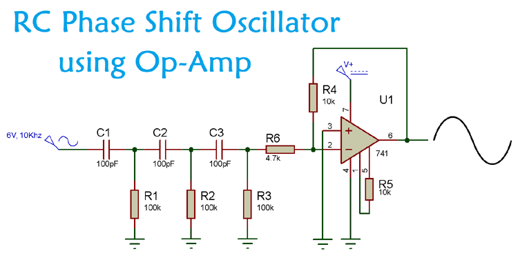
The RC Phase Shift Oscillator using Op-Amp is a classic analog circuit designed to generate a continuous sinusoidal waveform without requiring any external input signal. At its core, the circuit uses an operational amplifier configured as an inverting amplifier. The op-amp provides the necessary voltage gain to sustain oscillation, while introducing an automatic 180-degree phase shift between its input and output.
To achieve the total 360-degree phase shift required for positive feedback and sustained oscillation at a specific frequency, a feedback network composed of three identical resistor-capacitor (RC) stages is connected between the op-amp output and its inverting input. Each individual RC stage introduces a frequency-dependent phase shift. By cascading three identical stages using the specified 100kΩ resistors and 100pF capacitors, the network achieves an additional 180-degree phase shift at the frequency of oscillation, perfectly complementing the inversion introduced by the op-amp.
Resistors such as the 10kΩ and 4.7kΩ components are used to set the proper DC biasing and gain parameters around the LM741 op-amp, ensuring that the loop gain satisfies the Barkhausen criterion—meaning the gain is precisely unity at the oscillation frequency. As power is applied, ambient electrical noise is amplified, and the selective feedback network ensures that only a single frequency builds up into a stable, clean sine wave. An oscilloscope can be connected to the output terminal to visually monitor, measure, and analyze the resulting waveform's frequency and amplitude.
Why Build This
Design and analyze analog feedback loops and frequency-selective networks suitable for audio signal generators and function generators.
Gain practical laboratory experience using an oscilloscope to measure waveform frequency, period, and amplitude distortion.
Understand the application of the Barkhausen stability criterion in active operational amplifier circuits.
Real-World Application
Audio signal generators, musical instruments, function generators, clock generation for digital systems, and voice synthesis equipment.
Skills You'll Learn
analog circuit design
operational amplifier configuration
frequency response analysis
oscilloscope waveform measurement
feedback network analysis
Safety Precautions
No specific precautions noted for this build — always follow general electronics safety practices.
Technology Tags
OP-AMP
LM741
RC PHASE SHIFT OSCILLATOR
SINUSOIDAL WAVEFORM
ANALOG CIRCUITRY
FEEDBACK NETWORK
Frequently Asked Questions
An oscilloscope is necessary to visually observe the generated sinusoidal output, measure its frequency, and verify that the waveform is stable and free of clipping.
Each RC stage introduces a portion of the phase shift, and combining three stages provides the cumulative 180-degree phase shift needed to match the op-amp's inversion for positive feedback.
Yes, but changing the values will alter the oscillation frequency. All three resistor stages and all three capacitor stages should remain matched to maintain predictable behavior.
Gallery
This page is part of Kitkraft's Project Hub — a curated collection of electronics & robotics projects gathered from the maker community to help students and hobbyists discover and learn to build. Kitkraft does not claim authorship of the original project, and makes no representation as to the accuracy, completeness or safety of third-party source material. The summary and "How It Works" explanation above are AI-generated, rewritten with reference to the original tutorial — not a reproduction of it. Full credit and a direct link to the original source are provided above. If you're the original creator and have a concern about how your work is represented here, please contact us and we'll address it promptly.
 10pcs - 220 ohm 1/4 W Resistor Set
Rs. 39.00
 400 Points Mini Solderless Prototype PCB Breadboard High Quality
Rs. 89.00
 MB102 Adjustable Breadboard Power Supply Module (3.3V & 5V) for Arduino & Raspberry Pi
Rs. 139.00
 Jumper Wire 10 Pin Male To Male 20cm
Rs. 45.00
 Jumper Wire 10 Pin Male To Female 20cm
Rs. 45.00


