We stock the boards, sensors and modules this project needs. A full parts list is coming soon — for now, browse our DIY Kits & components or search for Analog / Discrete parts.
This project is sourced from another site, not written by us — this list is our best match of their components against what we stock, not a verified bill of materials. Always check the original blog (linked above) for the actual parts list before buying.
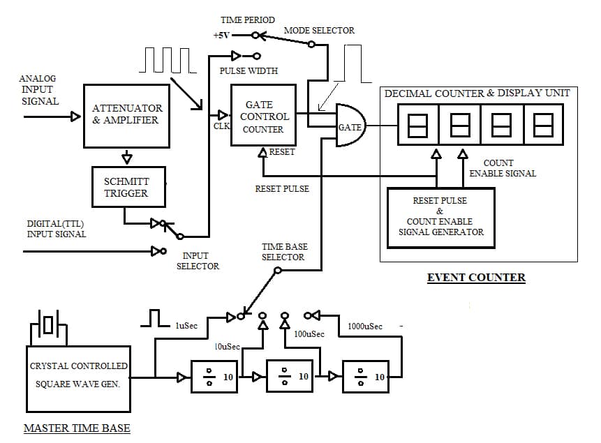
The Time Period Cum Pulse Width Cum Capacitance Meter operates by translating physical electrical properties into measurable digital counts and analog representations using foundational hardware blocks. When measuring time periods or pulse widths, an incoming signal is conditioned using operational amplifiers and Schmitt trigger ICs to square up the waveform edges, producing clean clock pulses. These pulses gate a reference frequency into counter-decoder logic chips, which accumulate the counts and drive the display components to show the resulting time or width. For capacitance measurement, the unknown capacitor is typically integrated into an analog timing network—such as an RC oscillator or monostable circuit—where its charge or discharge rate dictates the duration of a gating window. By measuring this window with the digital counter chain, the system determines and displays the capacitance value directly. Because this is built using discrete analog and digital integrated circuits without a programmed microcontroller, the entire operation relies on precise hardware timing, signal conditioning, and logic decoding.
Why Build This
Gain hands-on undergraduate-level experience integrating mixed analog and digital subsystems into a single test instrument.
Deepen your practical understanding of op-amp signal conditioning, Schmitt trigger hysteresis, and synchronous counter-decoder logic.
Construct a functional, multi-purpose laboratory bench tool to analyze waveforms and characterize passive components without relying on pre-built modules.
Real-World Application
Used in electronics laboratories, manufacturing quality control, and testing environments for analyzing waveforms, debugging digital circuits, and measuring component values.
Skills You'll Learn
operational amplifier signal conditioning
Schmitt trigger waveform squaring
counter-decoder logic cascading
analog timing network design
display component interfacing
Safety Precautions
Exercise standard electrical caution when working with mains-powered or bench power supplies.
Technology Tags
SIGNAL PROCESSING
ANALOG ELECTRONICS
DIGITAL ELECTRONICS
SCHMITT TRIGGER
TIMERS
MEASUREMENT INSTRUMENTATION
Frequently Asked Questions
No, this project is built entirely using analog components, operational amplifiers, and hardwired logic chips, so no software or programming is required.
Schmitt triggers provide built-in hysteresis, which cleans up noisy input waveforms and prevents false triggering by sharpening slow-rising signal edges.
The user manually or electronically reroutes the circuit configuration so that either an external signal is fed into the counter gating logic, or an unknown capacitor is connected to an analog timing network.
Gallery
This page is part of Kitkraft's Project Hub — a curated collection of electronics & robotics projects gathered from the maker community to help students and hobbyists discover and learn to build. Kitkraft does not claim authorship of the original project, and makes no representation as to the accuracy, completeness or safety of third-party source material. The summary and "How It Works" explanation above are AI-generated, rewritten with reference to the original tutorial — not a reproduction of it. Full credit and a direct link to the original source are provided above. If you're the original creator and have a concern about how your work is represented here, please contact us and we'll address it promptly.